Ford Parts Wiki | GM Parts Wiki
Home | Search | Browse | Marketplace | Messages | FAQ | Guest
Prev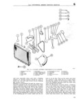
 Next
Next
G COOLING SYSTEM engine connections Insert flushing gun and flush rating specified It should never be altered or re heater core Care must be taken when applying air placed by a plain cap pressure to prevent damage to the heater core A Vacuum release Valve Fig G6 is Employed to G 2 Failing Cooling System prevent undesirable vacuum build up when the system cools down The vacuum release valve is Te fill the eeeling system rerneve the fill cap and held against its seat under light spring pressure fill the tank te ina tap Replace the Cap and run Vacuum in the system is relieved by the valve the engine at medium speed for approximately one which opeus at ie to 1 pgi 0 035 3 7 kg em2 minute Remove the Cal and reeheek the 00lant vacuum A pressure tester can be used to check and level Add more coolant if necessary to bring the test the vacuum pressure rate see Fig G 6 level back to th tOp of the tank the COOllI lg the mechanism Of the pyggguyg cap rg system is filled when the engine is cold 1 h k the quires no maintenance the cap should be inspected enelanr level after the engine has warmed up This periodically for cleanliness and freedom or opera will ensure that the thermostat has opened allow riou The pressure e3p gesket 3ud r3dr3tor filler ing C0lnPl t eeeling system iF la i0n neck seat should also be inspected to be sure they Always 0rr i any ceeling system leaks bainra are providing a proper seal If the rubber face of installing antifreeze A corrosion inhibitor should the V3 Ve is defective 3 new e3p shou d bg iustelled be used in the eeeling system fe Prayant the f0rina Filler neck reseating tools are commercially avail nan nf rust and seale A quality brand antifreeze able to correct minor detects at the surface or the lmntaining a eerresien inhibitor sheuld be used seat Follow instructions of the reseating tool manu When the antifreeze is drained in the spring a f3erurer corrosion inhibitor should be added with the water To remove the radiator pressure cap when the Note Cooling system components for both V6 and gnggfhczcggpttgimlgfgsiimze Lsagiggigr tliiiiiincgggugilgre F4 engmes are Shown m F1gS Glz and G 3 clockwise about turn until the first pressure release stop is reached Keep the cap in this posi G 3 Draining Cooling Sysrem tion until all pressure is released Then push cap To completely drain the cooling system open the 2 dm i Eggilitgiefufggsiiireuggll c C i Ot drain in the bottom of the radiator and also a tisn mid tum it Clockgise as farp spit will Op drain on the right side of the cylinder block on the Hurricane F4 engine The Dauntless V 6 engine Caution Use extreme care in removing the radiator has fW0 drain plugs one l0 at d on each side of pressure cap In overheated systems the sudden the cylinder block Both plugs must be removed to release of pressure can cause a steam flash and this completely drain the C00ling system flash or the loosened cap can cause serious personal Remove the radiator cap to break any vacuum iujury that may have developed Should the cooling solution be lost from the system and the engine become overheated do not refill G 5 RADIATOR the system immediately but allow the engine to Maintenance of the radiator consists of keeping cool or refill slowly while the engine is running If the exterior of the radiator core clean the interior cold solution is poured into the radiator while the free from rust and scale and the radiator free from engine is overheated there is danger of cracking the leaks Check the cooling system fluid level and for cylinder block and or cylinder head leaks each 2000 miles 3 200 km or every 30 days whichever occurs first This exterior of the G 4 Radiafor pressure Cap radiator core should be cleaned and the radiator All radiators are equipped with pressure caps which inspected for leaks feagh G0 mg 9600 hkmig reduce evaporation of cooling solution and make Of normal Sefvlce O t ve lc E h ezlmng S Ou the engines more efficient by permitting slightly be performed PY blowmg Out Wlt an Stream or higher operating temperatures When operating warersream sirenedfremthe reareftheradiater properly the pressure cap permits pressure build up Visual mspectmn is ret Sufflclfmt as the aCCumu1a in the cooling system during periods of severe heat UGH of small pafiucles if foreiilgn mateflal On com load This pressure increases the boiling point Of surfaces can restrict cooling without closing the core the coolant and thus reduces overflow losses The p IlmgS effectiveness of the cap is limited by its opening Raljlatcr leakage Occflonauy results from kew pressure and the boiling point of the coolant see mslon perforatlon Of t Q Wftal but most ge age note below The pressure cap employs a spring reiiults fren mschanlcaa fmbufe of jalderji Jplptts loaded rubber faced pressure seal which presses W en mo muc S tram 1 as ee pl 0n the 101 against a seat in the radiator top tank Spring pres Fr ctur incur gmst io will at t 8 Jomt gvde Ehe sure determines the opening pressure of the valve ignigto vgleit 3 sggfnitbliggi ia i esOl f joint is exposed and can corrode but breakage Note Refer to cooling system specifications Par rather than corrosion is the primary cause of seam G 21 for opening relief pressure when the ve leakage Examine the radiator carefully for leaks i hicle is equipped with either the Hurricane F4 before and after cleaning Cleaning may uncover or Dauntless V 6 engine If a new cap is required points of leakage already existing but plugged with always install a cap of the same type and pressure rust White rusty or colored leakage stains indicate 164