Ford Parts Wiki | GM Parts Wiki
Home | Search | Browse
Prev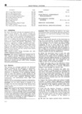
 Next
Next
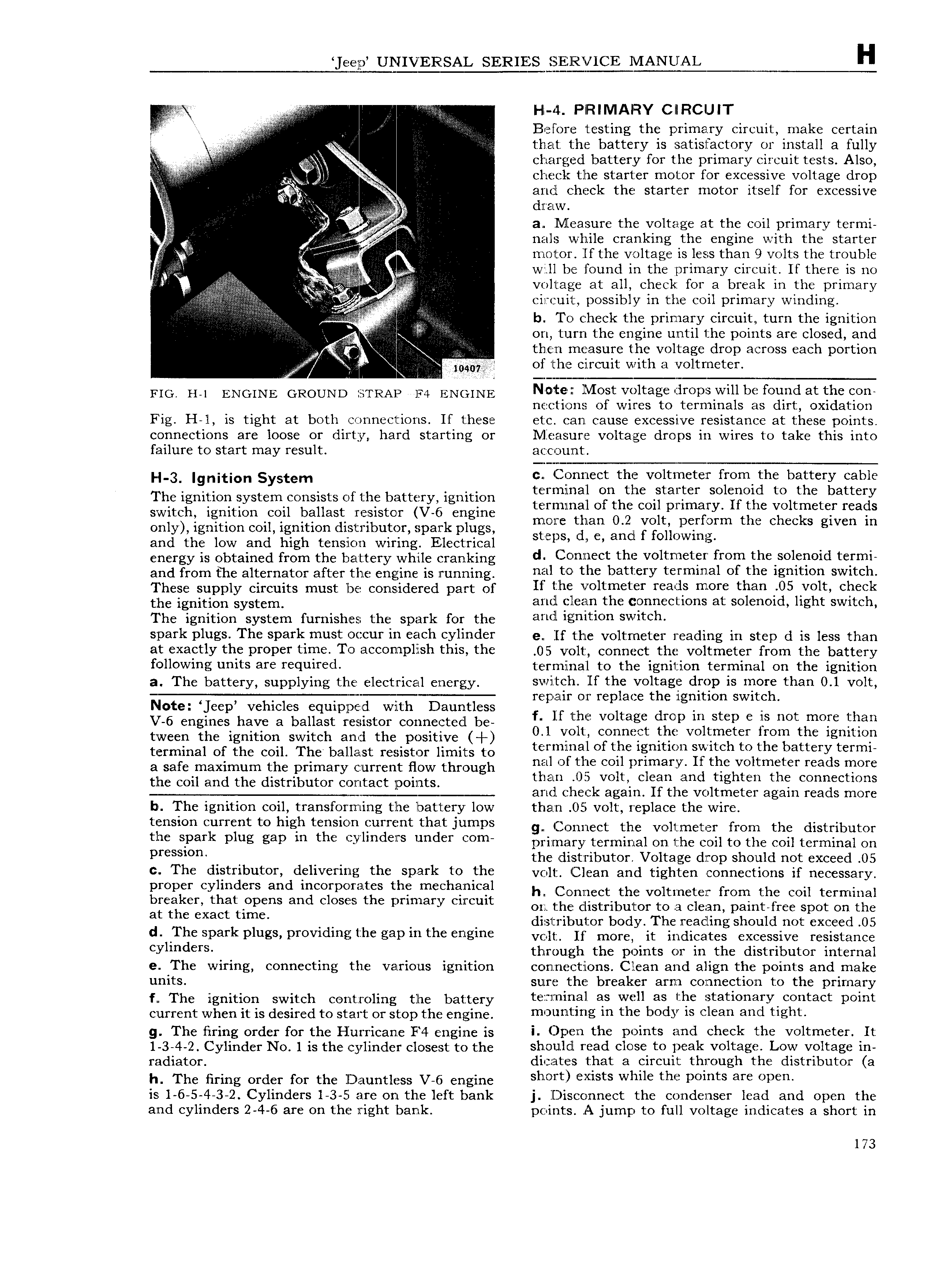
eep UNIVERSAL SERIES SjEilR l 1CE l IANUAL H Hl 4 PIRIMAIRY CIIRCIJIT w A i V it Before testing the primary circuit make certain that the battery is satisfactory or install a fully I charged battery for the primary circuit tests Also t i g ek i It A check the starter motor for excessive voltage drop i V and check the starter motor itself for excessive t t i Vti l dw a Measure the voltage at the coil primary termi ii A nals while cranking the engine with the starter j jj t r motor lf the voltage is less than 9 volts the trouble E iii g will bc i 0und in the primary circuit If there is ng W voltage at all check for a break in the primary circuit possibly in the coil primary winding i V i it i gy b To check the primary circuit turn the ignition S i V i i i i on turn the engine until the points are closed and J i i V tliifgl measurie thshvoltagte dtop across each portion E r0 ey o l ne clrcui wi a vo me er r x i FIG H i ENGINE GROUND itiTRAio F4 EN INE N OlltF lI lt3g CIYODS fOCl Hd at COH nections o wires to termina s as irt oxi ation Fig H l is tight at both connections If these etc can cause excessive resistance at these points connections are loose or dirty hard starting or l ljeasure voltage drops in wires to take this into failure to start may result accouznt i i 3 Ignition System c Connect the voltmeter from the battery cable The ignition system consists of the battery ignition Ki mmaii gn hthc ta l F r sOl Oid to the battery switch ignition coil ballast resistor V 6 engine tE H3m1i O B cO1itpHm ry talc Vifltillietgr mags only ignition coil ignition distributor spark plugs ngglc alan iz iii irm B C CC S gwcn m and the low and high tension wiring Electrical S pS C anc O OWml energy is obtained frern the battery Wh ne eranking d Connect the voltmeter from the solenoid termi and frorn the alternator after the engine is ii unning 1 1 51 t O the b3tiiCI y t l ITIII H1 of the ignition switch These Supply circuits must lbiti Consiidcrod part ef If the voltmeter reads more than 05 volt check the ignition system and clean the connections at solenoid light switch I he ignition system furnishes the spark for the ai ii21 iti it n Sipafk Plugs The Spafk must 0 i 1 iii C wh Cyiifldf f 0 If the voltmeter reading in step d is less than at exactly the proper time To accomplish this the 05 volt connect the voltmeter from the battery following units are required terminal to the ignition terminal on the ignition 3 The battery supplying the electrical eiyie i gy Switch If the VOlt8gl2 dI Op is II1OI than 0 1 volt Note eep vehicles equipped with Dauntless reipiiur OI mplahc the lgrimon swltfihi V 6 engines have a ballast resistor connected be f if Hm Voltage dwp In Step C is not mofc than tween the ignition switch and the positive l Ol YiOhL conmiict its Volimctcr from the lgmtwp terminal Of the Con The baiigast resistor limits to terminal of the ignition switch to the battery termi a safe maximum the primary current How through mil Of UF COI pmmarw If thc Voltmeter reads more the Coil and the distributor Contact ipoimsi than 0 l volt clean and tighten the connections and check again If the voltmeter again reads more b The ignition coil transforming the battery low than 05 volt replace the wire mansion Current to hlgh tcnslcm Yurmnt that Jumps g Connect the voltmeter from the distributor the spark plug gap m the vl d its under Com prirnary terminal on the coil to the coil terminal on pr Ss the distributor Voltage drop should not exceed 05 The distributor delivering the spark to the volt Clean and tighten connections if necessary giggiigrcgggfgeig Uig ifQ i fi fi t 1 h Connect the voltrneter from the coil terminal at the cgiact time F or the distributor to a clean paint free spot on the i distributor body The reading should not exceed 05 d The Spark Plu S PYOV1d n C the gap in the ngin volt If more it indicates excessive resistance CY1md YS through the points or in the distributor internal e The wiring connecting the various ignition cc nl nect ions Clean and align the points and make units sulre the breaker arm connection to the primary f The ignition switch eergrtrniing the battery tezrrnirlal as well as the stationary contact point current when it is desired to start or stop the engine m 9nn l ing in the bOd5 is clean and Ugh g The firing order for the I urrican e F4 engine is i Open the points and check the voltmeter It 1 3 4 2 Cylinder No 1 is the cylinder closest to the should read close to peak voltage Low voltage in radiator dicates that a circuit through the distributor a h The firing order for the lDauntless V 6 engine sh O Yt Smsts Whlle th points are Open is 1 6 5 4 3 2 Cylinders 1 3 Ei are on the left bank j l Z is connect the condenser lead and open the and cylinders 2 4 6 are on the right bank points A jump to full voltage indicates a short in 1173