Ford Parts Wiki | GM Parts Wiki
Home | Search | Browse | Marketplace | Messages | FAQ | Guest
Prev

 Next
Next
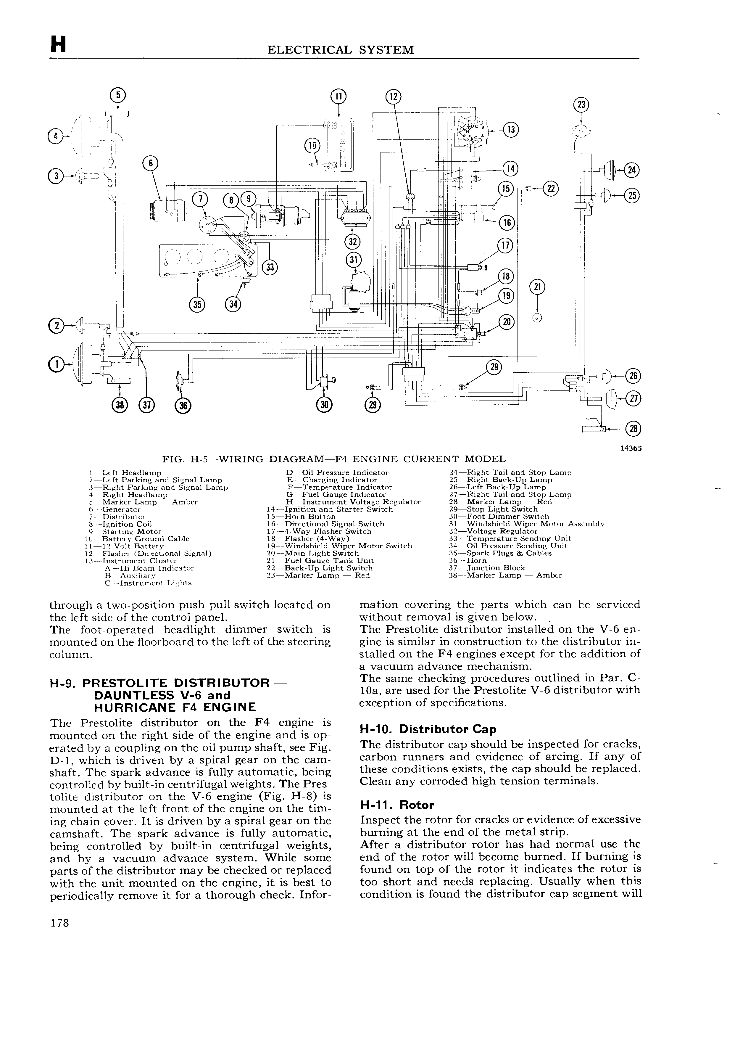
H ELECTRICAL SYSTEM lqjl QD 7 e r mr ii if QD i Cir U ri lfwiild P 7 N H Li 77 77 77 t I l Ll l li ll e it V i tt g 4 lug wl ji c w 1 4ji irjrkgfi T TL U Q 7 I 1 Q l U ULTYZTYT W l l Q ww 1 e 7 gn V I Illllr I M5 ll e is I is 7 l I DD 9 a l 7 7 m l li 7 L 1 i l I riiiglw lg g l g r7 I I ll7 l QD l 7 i W i 7 sa I Il V Vi i 7 7 77 7 g at ht l l 1 r rr nlm L ri w dl 7 IEll l l pl 7 Im T l 4 n il ca W lll ILI n 7 LEff iiiDiu Q 14365 FIG H 57WIRING DIAGRAM F4 ENGINE CURRENT MODEL l77Left Headlamp D7Oil Pressure Indicator 24 7Right Tail and Stop Lamp 277Left Parking and Signal Lamp E7Charging Indicator 2577Right Back Up Larnp 3 Righ Parking and Signal Lamp F7Te1nperature Indicator 2677Left Back Up Lamp 47 Right Headlamp G7 Fuel Gauge Indicator 277Right Tail and Stop Lamp 5 7Marker Lamp 77 Amber H Instrument Voltage Regulator 287Marker Lamp 7 Red n77 G D Y8tOf 147Ignition and Starter Switch 29 St0p Light Switch 77 7Distribut0r l57Horn Button 307F0ot Dimmer Switch 8 7Ignition Coil l677Directional Signal Switch 3l7Windshield Wiper Motor Assembly 077 Starting Ivlotor 17 74 Way Flasher Switch 32 V lt8g Regulator 1 7Battery Ground Cable l87Flasher 4 Way 337 Femperature Sending Unit 11712 Volt Battery 197 Windshield Wiper Motor Switch 347Oil Pressure Sending Unit 127 Flasher Directional Signal 207l Iain Light Switch 3S77Spark Plugs Cables 13777Instrument Cluster 2l7Fuel Gauge Tank Unit 367 7Horn A7 Ii Beam Indicator 227Baclc Up Light Switch 37 7 unction Block B 7Auxiliary 23 MHl k f Lamp 7 Red 3877Marker Lamp 7 Amber C instrument Lights through a two position push pull switch located on mation covering the parts which can be serviced the left side of the control panel without removal is given below The foot operated headlight dimmer switch is The Prestolite distributor installed on the V 6 en mounted on the floorboard to the left of the steering gine is similar in construction to the distributor in column stalled on the F4 engines except for the addition of a vacuum advance mechanism H 9 PRESTOLITE DISTRIBUTOR The same checking procedures outlined in Par 0C DAUNTLESS V 6 and 10a are use for tge Prestolite V 6 distributor with XC p C1OI l O Sp C1 C3t1OI 1S The Prestolite distributor on the F4 engine is mounted on the right side of the engine and is op H 10 Distnbutor cap erated by a coupling on the oil pump shaft seg Fig The d1SU 1bl1 CO1 Cap should be inspected for cracks D 1 which is driven by a spiral gear cn the cam carbon runners and evidence of arcing If any of shaft The Spark advance is fully autornatic being these conditions exists the cap should be replaced controlled by built in centrifugal weights The Pres Cleah ahy OU Od d hlgh t hSl0h t Yh hh31 tolite distributor on the V 6 engine Fig H 8 is mounted at the left front of the engine on the tim H 11 R t ing chain cover It is driven by a spiral gear on the Inspect the rotor for cracks or evidence of excessive camshaft The spark advance is fully automatic burning at the end of the metal strip being controlled by built in centrifugal weights After a distributor rotor has had normal use the and by a vacuum advance system While some end of the rotor will become burned If burning is W parts of the distributor may be checked or replaced found on top of the rotor it indicates the rotor is with the unit mounted on the engine it is best to too short and needs replacing Usually when this periodically remove it for a thorough check Infor condition is found the distributor cap segment will 178

 Next
Next