Ford Parts Wiki | GM Parts Wiki
Home | Search | Browse | Marketplace | Messages | FAQ | Guest
Prev

 Next
Next
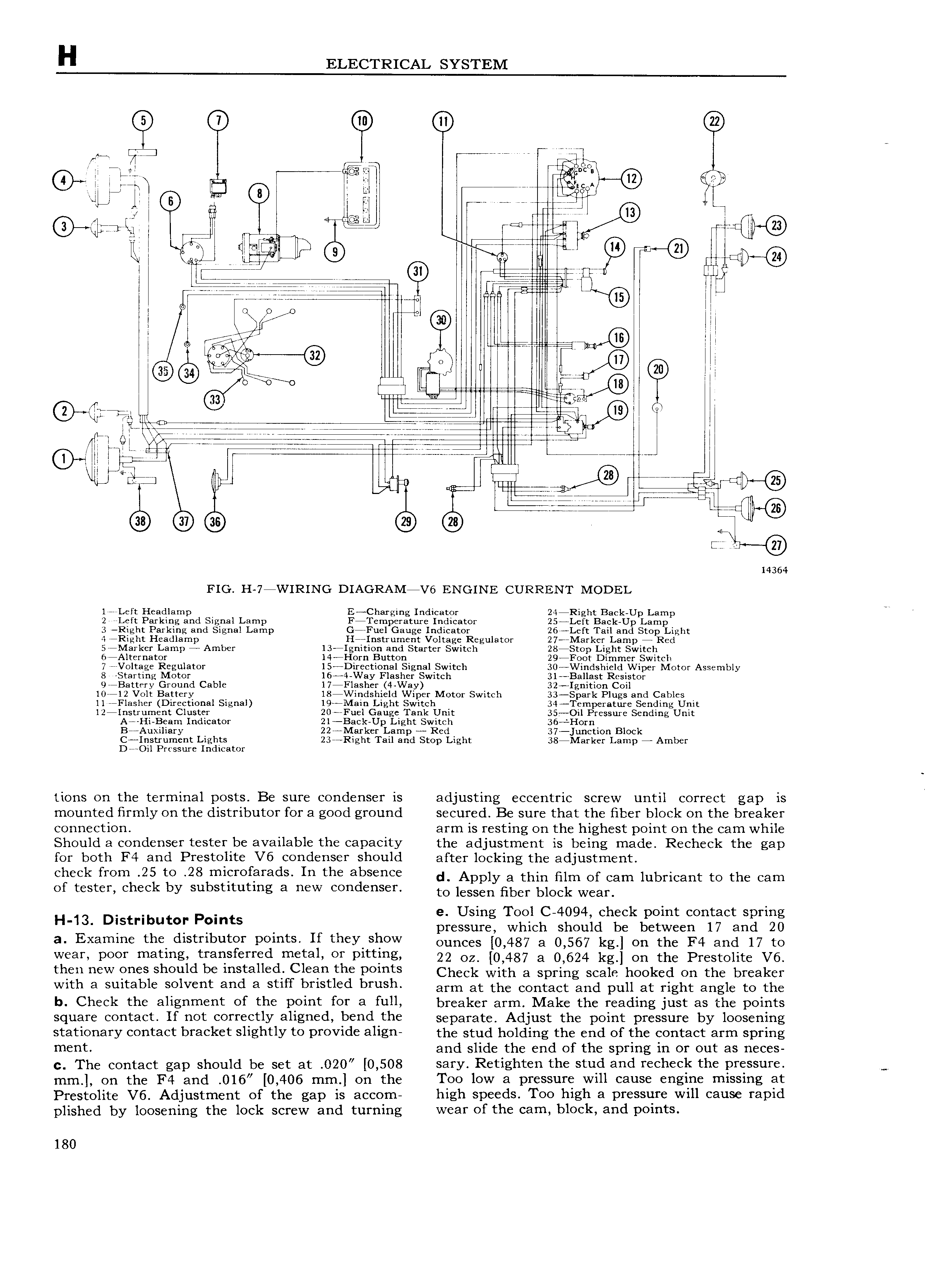
H ELECTRICAL SYSTEM ITF T pw www if r ii n cf T7 fi C U T TT T 77 7 7 rriiijj R QI T TT Ar TT TT 4TTa l T PF IT in T W W ill Tr QT 0 TTTET Q M 7 TT T T 7 7 ui he 777 no e T 77 T I 777 i i 7 T T T T T T T T T T T aa T 7 T TTT T ep nm TT 4 TQ T lHl H Y Q TT T 33 w I r le T a SS S 77 an gE T TT TT TT cw 73 i ITV T L4 Ti 7 ITT 7 7 77 7 7 7 i 7 7 Y Q Ti T AT tTQT 77i7 7 7 e LLLL i T T TT 4 In wwWM w A i s T r t N LT T u TT Tl lT T E if oro e e a T TTTT F T 4 l7 FW T 14364 FIG H 7 WIRING DIAGRAM V6 ENGINE CURRENT MODEL 1 Left Headlamp E Cha rging Indicator 24 Right Back Up Lamp 2 Left Parking and Signal Lamp F Temperature Indicator 25 Left Back Up Lamp 3 Rrght Parking and Signal Lamp G 7Fuel Gauge Indicator 26 Left Tail and Stop Light 3I hi J EZ Amb T is f iQf s 3 tR g r i f kE i Q ThR d 7 l 7 C 77 nl 1011 HH B 7 V 6 Alternator P 14 I 0rn Button I Cr wl L 29 Fo f I mmelivS itch g mg gltgge I eg xlator g ecti al Eigrgal Swatch g0 gViSds 1gd iper Motor Assembly H1 l O Of 7 8 BS E 1 77 77 O B Cf 7 ll S 1 l C 7 zee w 1 r a z m y S T ii OL C 11 Flasher Direczional Signal 19 Main Light Swlitdh 0 or wl C 34 Tg iperatx1 e8Sxendi i1gCI Init 12 IXs i iIm nt Cliisger t 7gueL 1u Ting g gil Pressure Sending Unit 7 1 BETH H ICH OT 7 HC I 1 7 B 4Auxiliary 227 MarkerDLar p wReii 37 jucii3 i0n Block I gi t li ument Iiiggts t 23 Right Tail and Stop Light 38 Marker Lamp 4 Amber 7 l l SS 1I D ICB OX tions on the terminal posts Be sure condenser is adjusting eccentric screw until correct gap is T mounted firmly on the distributor for a good ground secured Be sure that the fiber block on the breaker connection arm is resting on the highest point on the cam while Should a condenser tester be available the capacity the adjustment is being made Recheck the gap for both F4 and Prestolite V6 condenser should after locking the adjustment check l iI OI l l to ITl1CI Of3I 3dS In th 3bS I 1C d 8 thin Of Cam lubricant tO the Cam of tester check by substituting a new condenser to lessen nber block Wear e Using Tool C 4094 check point contact spring H 13 D StHbut r P mts pressure which should be between 17 and 20 a Examine the distributor points If they show ounees 0 487 3 0 567 kg on the F4 and 17 ro W 3Y POOY matlng tm TSf d m t31 OY Pitt g 22 oz 0 487 a 0 624 kg on the Prestolite V6 then new ones should be installed Clean the points Cheek with 8 Spring Scale hooked on the breaker with a suitable solvent and a stiff bristled brush arrn at the eontaet and pull at right angle ro the b Chcck thc 3l1g1 1m cf thc P01 OY 8 full breaker arm Make the reading just as the points Sq 181 C0 3 t If not C0IT flY 8hg d b d h separate Adjust the point pressure by loosening stationary ccntact brackct Slightly tc prcvidc align the stud holding the end of the contact arm spring ment and slide the end of the spring in or out as neces c The contact gap should be set at 020 0 508 sary Retighten the stud and recheck the pressure mm on the F4 and O16 0 406 mm on the Too low a pressure will cause engine missing at Prestolite V6 Adjustment of the gap is accom high speeds Too high a pressure will cause rapid plished by loosening the lock screw and turning wear of the cam block and points 180

 Next
Next