Ford Parts Wiki | GM Parts Wiki
Home | Search | Browse | Marketplace | Messages | FAQ | Guest
Prev

 Next
Next
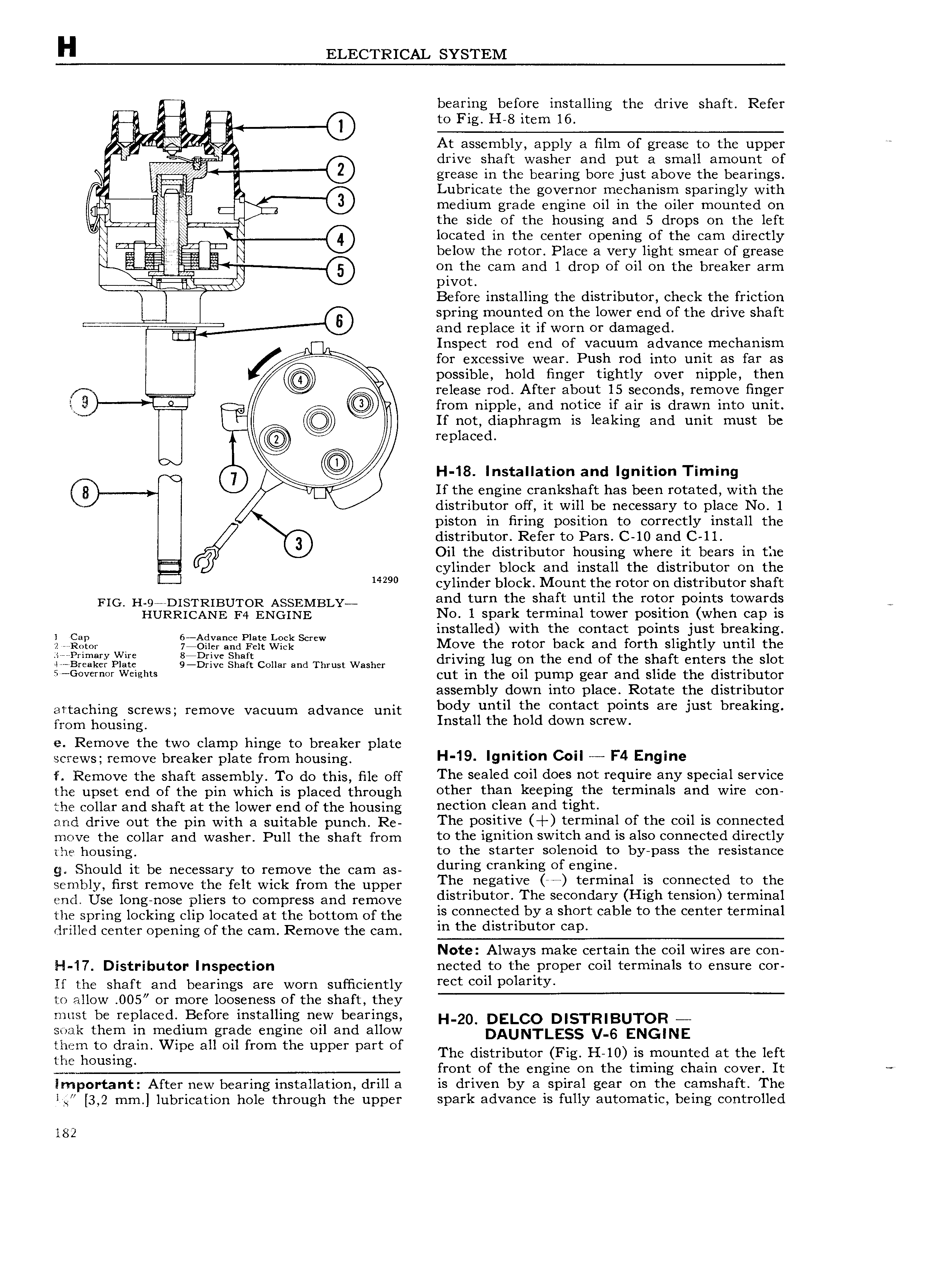
H ELECTRICAL SYSTEM I I bearing before installing the drive shaft Refer to Fig H 8 item 16 2 i At assembly apply a film of grease to the upper l drive shaft washer and put a small amount of 0 grease in the bearing bore Just above the bearings q 2 Lubricate the governor imechamsm sparingly with mgis medium grade engine oil in the o1ler mounted on l m the side of the housing and 5 drops on the left I V I located in the center opening of the cam directly a below the rotor Place a very light smear of grease 6 on the cam and 1 drop of oil on the breaker arm i Tii pivot Before installing the distributor check the friction 8 spring mounted on the lower end of the drive shaft ZH 4 and replace it if worn or damaged nun A Inspect rod end of vacuum advance mechanism I for excessive wear Push rod into unit as far as possible hold finger tightly over nipple then V I release rod After about 15 seconds remove finger i 3 L1 Q V from nipple and notice if air is drawn into unit i u If not diaphragm is leaking and unit must be replaced 0 CD H 18 Installation and Ignition Timing 0 v If the engine crankshaft has been rotated with the distributor off it will be necessary to place No 1 piston in firing position to correctly install the 9 distributor Refer to Pars C 10 and C ll Oil the distributor housing where it bears in the cylinder block and install the distributor on the 14290 cylinder block Mount the rotor on distributor shaft FIG HQADISTRIBUTOR ASSEMBLY and turn the shaft until the rotor points towards HURRICANE F4 ENGINE No 1 spark terminal tower position when cap is I Cup 6 Advanc pim Lock Screw installed with the contact points just breaking 2 eenntnt 7 Oiler and Felt wiek Move the rotor back and forth slightly until the Li o i Y 2 3iB i Z ceiiai M Thrust wine driving lug the d f the shaft eiitefs the slot G v r or Weights cut in the oil pump gear and slide the distributor assembly down into place Rotate the distributor attaching screws remove vacuum advance unit body until the contact points are Just breaking mm housing Install the hold down screw e Remove the two clamp hinge to breaker plate H 19 I t c I F4 E screws remove breaker plate from housing gfll ION I ngme Remove the shaft assembly Te do this Bk gff The sealed coil does not require any special service the upset end of the pin which is placed through othei thin k P g h Yml l and wire 0 the collar and shaft at the lower end of the housin lil0 C 3 all UE and drive out the pin with n suitable punch Reg The positive terminal of the coil is connected move the collar and washer Pull the shaft from to tlie ignition switch aciid is also conneicted directly ine hOusmg to t e starter so enoi to y pass t e resistance g Should it be necessary to remove the cam as during erapkmg of engme sembly first remove the felt wick from the upper The Pegatlve e tepmmal S t l to the end Use long nose pliers to compress and remove elstrlbuten The Seeendary High tension terminal the spring locking clip located at the bottom of the S Connected by 3 Sheet cable to the eenter terminal drilled center opening of the cam Remove the cam m the dlstnbuter eap Note Always make certain the coil wires are con H I7 Distributor Inspection nected to the proper coil terminals to ensure cor If the shaft and bearings are worn sufficiently rect coil POlaY1tY to allow OO5 or more looseness of the shaft they must be replaced Bef ore installing new bearings I I 20 DELCO DISTRIBUTOR slizik theigi in ngieldiumugraflg engine oil and alitovii DAUNTLESS V 6 ENGINE iii QOtipSin p pp 3 mm p upper ppf O The dietnhutei Fig H 10 is mounted at the left front of the engine on the timing chain cover It Important After new bearing installation drill a is driven by a spiral gear on the camshaft The il 3 2 mm lubrication hole through the upper spark advance is fully automatic being controlled l82

 Next
Next