Ford Parts Wiki | GM Parts Wiki
Home | Search | Browse
Prev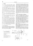
 Next
Next
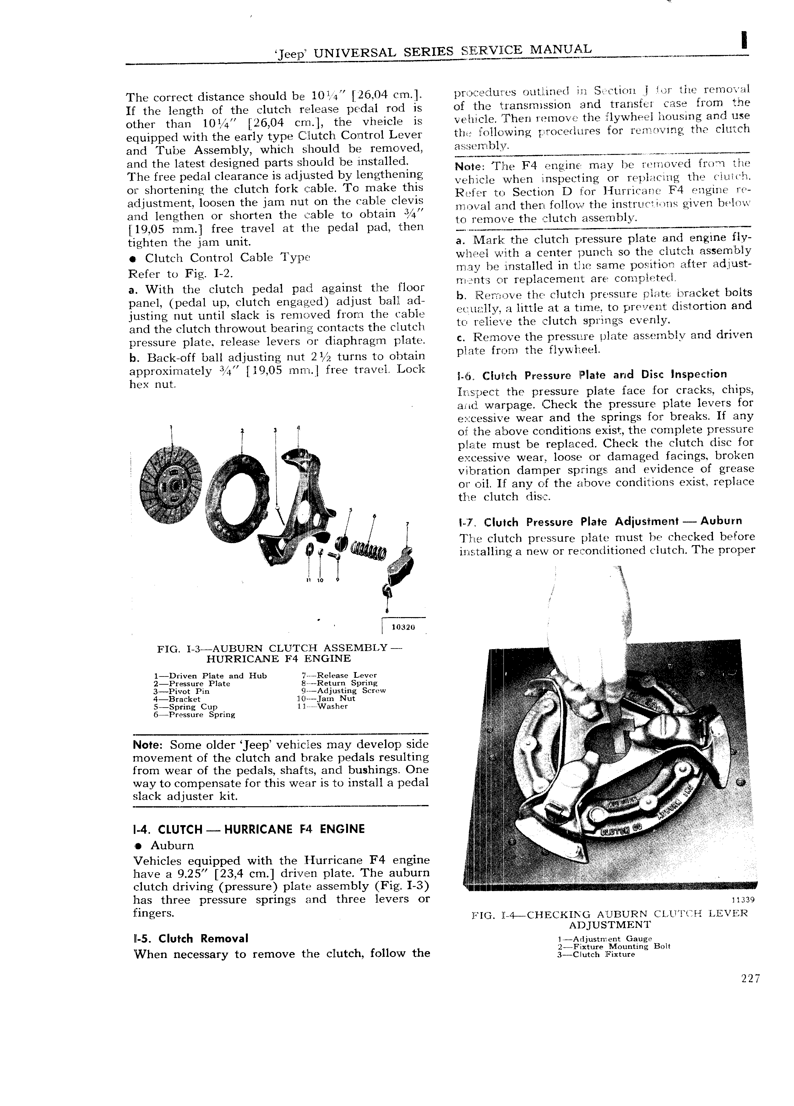
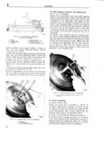
eelp UNIVERSAL IVIANUAL Wrwmw I Th 3 Corrrlct distance Should be 10 it 4 26 04 C m pr erlures ou tl ine l in Sactirwiil rl lor l Ilt I I llO kil If the length of the clutch release pedal rod is of the transmission and rtranster case rorn me ot her than 10l 4 26 04 ern the vheiele is velucllc ll hen remove the irlywheel housing and llse equipped with the early type Clutch Control Lever the 7 ll 0 lVm I l tlW OY Y YV Vm2 lll CI ll and Tube Assembly which sliould be removed l t9 7mlY ITl m 4 V r 4 M amd the latest d S g d parts lilhlcluld i SYa l N te The F4 engine may be removed frmrn the The free pl dal Clearance ls ad ljSt d li lengtk m g vehflcle when inspecting or replacing the clul ch Olbshort nlmg the Clutch fork l ab1 O ma 6 t lg Refer to Section D for l Iurricar e F4 engine rc 3d luStm nt IOOSQH the Jam mint On the Cable Clevlfi rnoval and then follow the iristirucfiwns given below and lengthen or shorten the cable to Obtam 41 V l to remove the clutch assernb y 19 05 mm free travel at the pedal pad then e tighten tlhe jam unit a Marl the clutch pressure plate and engine fly Clutch Crmrrol Cable l ylr r whl e l wlth a center punch so the clutch assembly Refer to Fig L2 may be mstalled in the same position after adjust l I i tv 5 l nt a cornnleteeil a With the clutch pedal pacl against the liloor Q I a aC i n I SX rlxwifk m k t bolts panel pedal up clutch engaged adjust ball ad IK lu il wi I j dl q ftiOn and justing nut until slack is reniicrved from the cable L EA tal l T inO4 p v I l1 and the clutch throwout bearing contacts the clutch W l U Q U C 1 SPL g C y p r SSur pl3r release levers Or rllrlphragm platgr c Iwlemove the pressure plate assembly and driven b Back off ball adjusting nut 2 turns to obtain plnmg fm the Hy il Q l r 1 3 190 fw t rel L l r Eggrgilrrletey 4 I r 5 mm I 66 0C l lg l r l r l 1 Pressure lplare and Disc nspe f I1 rsjpec t the pressure plate face for cracks chips and war va e Check the ressure plate levers for I E P Z I ZE Si l1V wear and the springs for breaks If any T l ll ol the above conditions exist the complete pressure V l pllaite must be replaced Check the clutch disc for l l ral e cessive wear loose or damaged facings broken l T vll 1 r ation damper springs and evidence of grease Z l or oil If anv of the above conditions exist replace le r rg tlpe lu tch dns 2 if il A l z I X7 Clutch Pressure Plate Adjustment Auburn l iT W lle clutch pressure plate must be Ch CI d b l0f A Q V insrtal1 irtl a new or reconditioned clutch The ro ner WI g I l e nl ro l Y E 3 rr I rz Z9 FIG I 3 AUBURN CLUT C I ASSEIVIBLY 1 I HURRICANE F4 ENGINE i 1 Drive Plate and Hub 7 Rele ase Lever I iii 2 Px essure Plate S Return Spring P i tt V 3 Piv0t Pin l Adjusting Screw lik I 4 Br aCket 1lU am Nut 5 SP CUP llrrwashef 6r r eS Smeg e ll Note Some older eep vehlctles may develop sidle E 1 jr r Vr A i movement of the clutch and brake pedals resulting ti l af t ig from wear of the pedals shafts and bushings One V V2 li way to compensate for this wear is to install a pedal g Q ti r iri V Vt t slack adjuster kit l I I i I 4 CLUTCH HURRICANE F4 ENGINE y r l i l t s eeeisj Vehicles equipped with the Hurricane F4 engine have a 9 25 23 4 cm driven plate The auburn l CIUtCI 1 dI IVlIlg pI SSuI plate assernbly Fig 1 3 l H 3 lrlr v has three pressure springs and three levers or 339 lfiflg fs wr 4 QHECKINCr AUBURN CL U iH LEVER AD lUSTMEN I Il 5 Clufch Removal 1 Adjustment Gaug eB r nw a When necessary to remove the clutch follow the glilIEi e1r irlggging OH 227