Ford Parts Wiki | GM Parts Wiki
Home | Search | Browse
Prev

 Next
Next
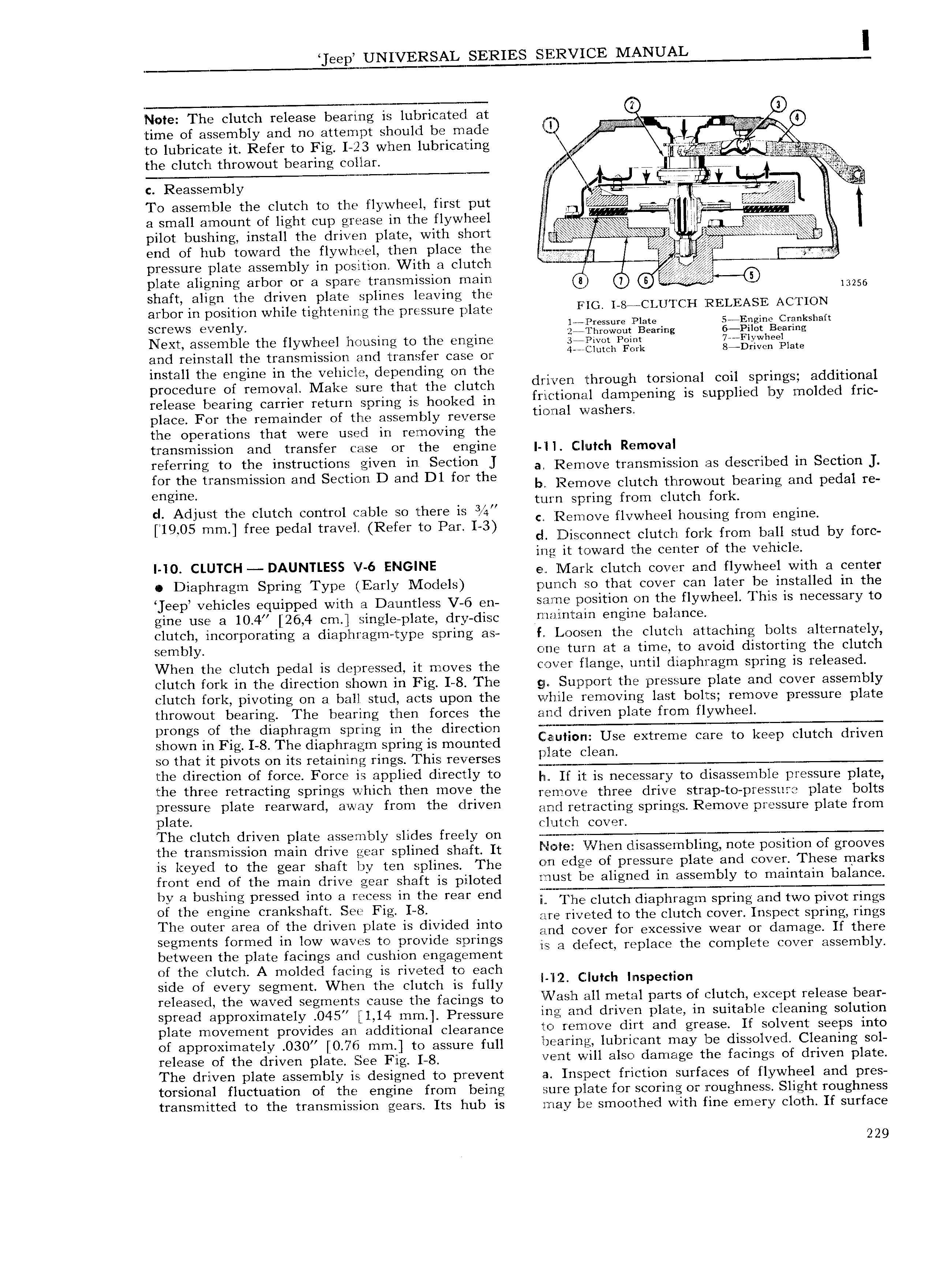
eep UNIVERSAL SERIES MANUA I Note The clutch release bearing is lubricated at y 7 I Q 4 time of assembly and no attempt should be made i 2 J to lubricate it Refer to Fig I 123 when lubricating ipp imp the clutch throwout bearing collar i gm 4 Wi a y i c Reassembly V ci 5 e Y V To assemble the clutch to thle flywheel first put it t 3 1 I l3ll 8imOUI 1 C of light Cup grease in the flywhee is dg at lip p i g s ls p pilot bushing install the driven plate with short y 2 end 0f hub toward the flywheel then place the I Vp V pressure plate assembly in position With a clutch plate aligning arbor or a spare transmission main 8 6 5 13256 shaft align the driven plate splines leaving the T V arbor in position while tightening the pressure plate Fic i 8e CiaUriiCi i RELEASE CTION Saws ae ry 1 r5 2tx Pa as r S a Next assemble the flywheel housing to the engine 3 rzgjrwt pom vu Fiywhesi and reinstall the transmission and transfer case or 4 i d F d STDHVCD Plate cle l r 2 Zifgigriigivaiieivigig iii iQr i ii i iiiii iiluiigir dwaa thrdugh tdraiaaal cad S i r sS addlaaaai mleasc bearing Carrier mmm Spring is hookeid in fri r tioria l dampening is supplied by molded fric place For the remainder of tlie assembly reverse tieiiei Washers the operations that were used in removing the transmission and transfer case or the engine 1 Clutch Removal reierring td tne instriietiOns given in Seetinn J a Remove transmission as described in Section for the transmission and Section D and Dl for the by Remove clutch thmwout bearing and pedal r Qngmd N turn spring from clutch fork iiiQi ixitnflffs t id i ii3Edgjgr iiigeigaiii 13 c Remove flvwheel housing from engine i J i i d Disconnect clutch fork from ball stud by forc ing it toward the center of the vehicle i i0 CLUTCH DAUNTLESS V 6 ENGINE e ll lark clutch cover and flywheel with a center Diaphragm Spring Type Early l Iodels punch so that cover can later be installed in the eep vehicles equipped with a Dauntless V 6 en same position on the flywheel This is necessary to gine use a 10 4 26 4 cm single plate dry dis q mziirxtain engine balance dutch incorporating 3 di3Pl11 Hg1T1 type Spring as f Loosen the clutch attaching bolts alternately sembly one turn at a time to avoid distorting the clutch VVhen the clutch pedal is depressed it moves the V r flange Until rii3Pi ir3 gm spring is reieeseii clutch fork in the direction shown in Fig I 8 The gy Support the pressure plate and cover assembly clutch fork pivoting on a ball stud acts upon the while removing last bolts remove pressure plate 1 hrowout bearing The bearing then forces the and driven plate from flywheel prongs of the diaphragm spring in the direction j T Shown in Fig I 8 The diaphragm Spring is mmmtgd ElLIl IOI I2 Use extreme care to keep clutch driven so that it pivots on its retaining rings This reverses ine tiireetien et tOree Feree ia eppiieti direeiiY td Ii If it is necessary to disassemble pressure plate ine three retreeting springs Wiiien than ineve the remove three drive strap to pressure plate bolts lpreis ire Piete reervverd e W iY treni tne eiriven arid retracting springs Remove pressure plate from jp a e cli c e The clutch driven plate assembly slides freely on i ij 2 tho trarismissiori Hain drivo gear spiipod Sh tft It Nom When disassembling note position of grooves is keyed to the gear shaft by ten splines The Crri edge or pressure Piete a d eever Tnese rnerks root arid of tha mam drivo goar shaft is piiloteid must be aligned in assembly to maintain balance by 3 bushudg pressed mm d mceee m the rear ddd E The clutch diaphragm spring and two pivot rings of the engine crankshaft See Fig I 8 a are riveted to the clutch cover Inspect spring rings The Outer area Ofrdie dnl ed plete is divided inte and cover for excessive wear or damage If there segments formed in low waves to provide springs is 3 dgifgch replace the Complete COVE assembly between the plate facings and cushion engagement of the clutch A molded facing is riveted to each side of every segment When the clutch is fully i i 2 mulch Iin p9cii n released the waved segments cause the facings to ivvrisin eii rnetei Parts Ot eiiiten exeept reieese been sproad approximately 045 Lia mm Prtassur mg and driven plate in suitable cleaning solution plate movement provides an additional clearance ie rerneve dirt arid grease it seivent seePs inte of approximately 3 7t mor to assure ful hearing lubricant may be dissolved Cleaning sol roioaso of tho drivori plat goo jig g verit will also damage the facings of driven plate The driven plate assembly is designed to prevent Inspect friction surfaces of flywheel and pres torsional fluctuation of the engine from being sure plate for scoring or roughness Slight roughness transmitted to the transmission gears Its hub is may be smoothed with fine emery cloth If surface 229

 Next
Next