Ford Parts Wiki | GM Parts Wiki
Home | Search | Browse
Prev

 Next
Next
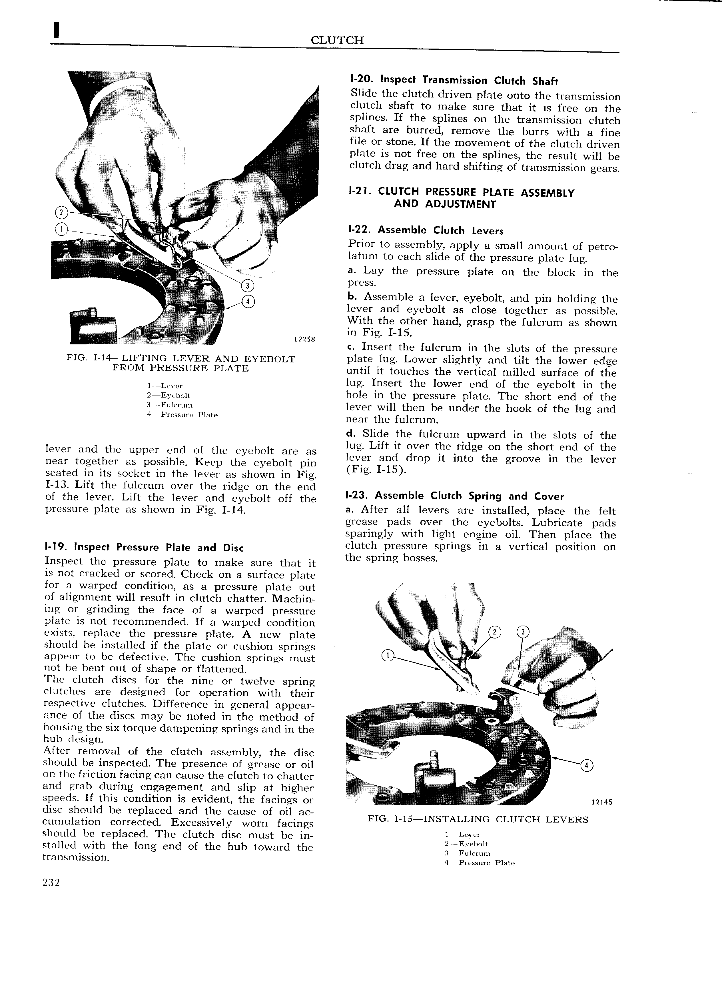
I CLUTCH I 20 Inspect Transmission Clutch Shaft E Slide the clutch driven plate onto the transmission V clutch shaft to make sure that it is free on the r splines If the splines on the transmission clutch ii if shaft are burred remove the burrs with a fine VV iziur r file or stone If the movement of the clutch driven Q plate is not free on the splines the result will be M Y A l I E clutch drag and hard shifting of transmission gears f ii j f a s ii e I 21 crurcu Pnzssuma Puma Assrmmv i i V l pbs AND ADJUSTMENT l e e l5 E l 1 r e A I 22 Assemble Clutch LGVGYS 1 r P t bl l ll f V r Vlvi g gv rior o assem iy app y a sma amount o petro Vvg A ref g J latum to each slide of the pressure plate lug I i i ij r lgllgll Qj a Lay the pressure plate on the block in the V 9 press b Assemble a lever eyebolt and pin holding the lever and eyebolt as close together as possible iiii f V g With the other hand grasp the fulcrum as shown i 12258 c Insert the fulcrum in the slots of the pressure FIC 4 L FTING LEVER AND EYEBOLT plate lug Lower slightly and tilt the lower edge FROM PRESSURE PLATE until it touches the vertical milled surface of the 1 Lcvcr lug Insert the lower end of the eyebolt in the 2 Eyebolt hole in the pressure plate The short end of the 3 Fu1 r m lever will then be under the hook of the lug and 4 P Plata near the fulcrum cl Slide the fulcrum upward in the slots of the lug Lift it over the ridge on the short end of the lever and the upper end of the eyebolt are as near together as possible Keep the eyebolt pin Q im dwp It mm the groove m the lever seated in its socket in the lever as shown in Fig g i 1 13 Lift the fulcrum over the ridge on the end of the lever Lift the lever and eyebolt off the l 23 Assemble clutch Sprmg and C V r pressure plate as Shown in Fig 14 a After all levers are installed place the felt grease pads over the eyebolts Lubricate pads sparingly with light engine oil Then place the 9 Inspect Pressure Plate and Disc clutch pressure springs in a vertical position on Inspect the pressure plate to make sure that it the Spring bOSS S is not cracked or scored Check on a surface plate for a warped condition as a pressure plate out E of alignment will result in clutch chatter Machin i ing or grinding the face of a warped pressure iii V plate is not recommended If a warped condition V iii r r Pzag 2 exists replace the pressure plate A new plate 2 r should be installed if the plate or cushion springs 1 r i W gr appear to be defective The cushion springs must rll i l not be bent out of shape or flattened X The clutch discs for the nine or twelve spring E H ii i r clutches are designed for operation with their respective clutches Difference in general appear r Z r ance of the discs may be noted in the method of Li i g housing the six torque darnpening springs and in the iii A hub design After removal of the clutch assembly the disc iii wir should be inspected The presence of grease or oil TW on the friction facing can cause the clutch to chatter V i J and grab during engagement and slip at higher V I A i V A l speeds If this condition is evident the facings or i rr 12145 disc should be replaced and the cause of oil ac FIG I 15 INSTALLING CLUTCH LEVERS cumulation corrected Excessively worn facings should be replaced The clutch disc must be in L l stalled with the long end of the hub toward the lI 3HSfT1lSSlOI 1 4 Pressure Plate 232

 Next
Next