Ford Parts Wiki | GM Parts Wiki
Home | Search | Browse
Prev
 Next
Next
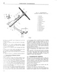
e ep UNIVERSAL SERIES NIANUAL 1 TI IZREIEZ SPlE ED TRHIEIEBII IISSION Contex1 l s l SUBJECT PAR SUBJECT PAR GENERAL l DllS ASEElEMBLY OF CANE J I r ESlHlIF T TRANSMISSION 8 l 2 jlo TRANSMISSION SHIFTlIl l L CONTROL l 2 Tmnsimission Cleaning and TRANSMISSION REIVIOTIEI Inscpection 4 l lll l8 CONTROL AD lUSTMEN I 3 Transmission Interlocking Remote CONTROL D1sAssr ilv1B1 Y 5 4 l i I Sp M log s l RlEEASS EMBLY OF CANE SHIFT t l S Y FEMOTE LONTROL REA FMBLY I 5 i RANsMissioN in iii Jie TRANSMISSION REMOVAZL l 6 SIELQVRVICE DIAGNOSIS 2O SEPARATING TRANSMIl 1 lION AND TRANSFER CASE J 7 I lE EL A NSMISSION SPECIFICATIONS I 21 Jl l GENERAL the remote control levers Check for binding of A three speed synchromeshlrarlsrnission is standard tim mmote Cfmtml Shaft On the l l l g Polumn oqulnrnonr on all nlooni Unlvor sul Vol llolosu and make the necessary corrections to eliminate The models TQO and T96 I1l l l IlSf1 lISSiOI IS are used alfly bm d ng COndlt l n vvlteh lno Hurrlonno F4 onglnoy andl modelfg TgoAA Il the shift is not smooth and positive first make and Tl lA transmissions are usled with the Dauiit Sl 1l the gears are IH neutral position then remove less V 6 engine All model transmissions are similar trlilli Sl ft rods at the transmission by removing in design with exception of the I l4 A which is 3 lf 1 T 1T1S F1l 7l l No 17 and slip a short piece fully synchronized all forward gears transmission Oil Snug fitting let 6 35 mm I 6l1E mg YOCI lZhr0 gh with helical drive gears tliroughoulg tlIll 5 gleairshlft levers and housing as shown in insert The transmission assembly is attaclhed to the rear lf l VVl t face of rho lyuinool lroll housing und is Sunnortod This places the clutch and shift lever assemblies on n rubloor insulator at rlro ru rno non tor Cross in the neutral position Adjust the shift rod yokes member which forms the rear engine suppore at the transmission end so clevis pins can be in All 4 vtheel clrive vehicles are equipped wilth 3 sta l led freely without moving the shift levers on the liyansfglc Cggg attached tcl fear the trams I lZ Z3 lf1SIlf llSSIOI 3fIZ 1 J VilI1CI I I DT1OVC8llgf1T1T 1llZ pil mission Transfer case service and repair procedures lf S lTl1 ftln1 from firilt to secondlis difficigt or transd are dgscylbgd ln Sgctlgltl I I l ll SiSIOI I angs II IYSL gear S OFIQCII t C OW an Models C 5A and C 6A are equipped with the reverse shift rod one turn at a time until the con same transmission but with a remote control shift clition is corrected Usually three turns are re IX Iodels D 5 and D l 6 are equipped with a similar C IQl lI Cl l transmission however the c nstruction is some SllTl Ol1AlCI the fault continue after completing the what different because it is not designed to above adjustment check further ras outlined below receive a transfer case for fo1 rr wheel drive First remove the lubnicating fitting U se a narrow For DIS and D 6 2WD vehicles the ttr3hs f l er gauge which will enter the opening for the mission repair procedures begin with Pap 1 ig lli l ri agtol arxlf checli ttle clelalrarncf between tig aces o1 t e s i ting utc ies is cearance s ou J 2 TRANSNIISSION SFIlIlI TIlN G CONTROL lie Ol5 to 031 MQ to 0 3974 794 mm If The shift of the threespeed tra nsrnission is siinogth this Clearance is greater the assembly must ibe and positive The cane control lever shiftsthe 1 r ms removed for adiustment The shift dog which rnission gears direct from the shift control housing vll l L the Cll lt h l t Sholild HOT haV mOY than mounted to the top side of the transmission housing l 9 Il 229 mm l l 3Y3 m the l0t If thi l 3f The remote control lever shifts the transmission 2 l1 lCZ between the clutch grooves and cross pins is gears through remote control rods attached to the 1100 g r at these DBMS mllSt be replaced adjusting levers of the shift shafts protruding from the left side of the transmission housing Poppet mll Ilqlcmoval of Rlemclte Control lballs and springs retain the transmission gears in Fr l C 5 A C sA rnesh and an interlocking mechanism prevents u y J lb shifting into two gears at the same time l lR l f to F12 J Z Y t remove the remote control the following pro J 3 Transmission Remote Control rurjlrrro is Suggested Adjustment tan Remove shifting rods from the transmission EQYIY C Io5A C l 6A iaalnd also from the steering remote control clutch First disconnect the transmission shift rods from levers 239