Ford Parts Wiki | GM Parts Wiki
Home | Search | Browse
Prev
 Next
Next
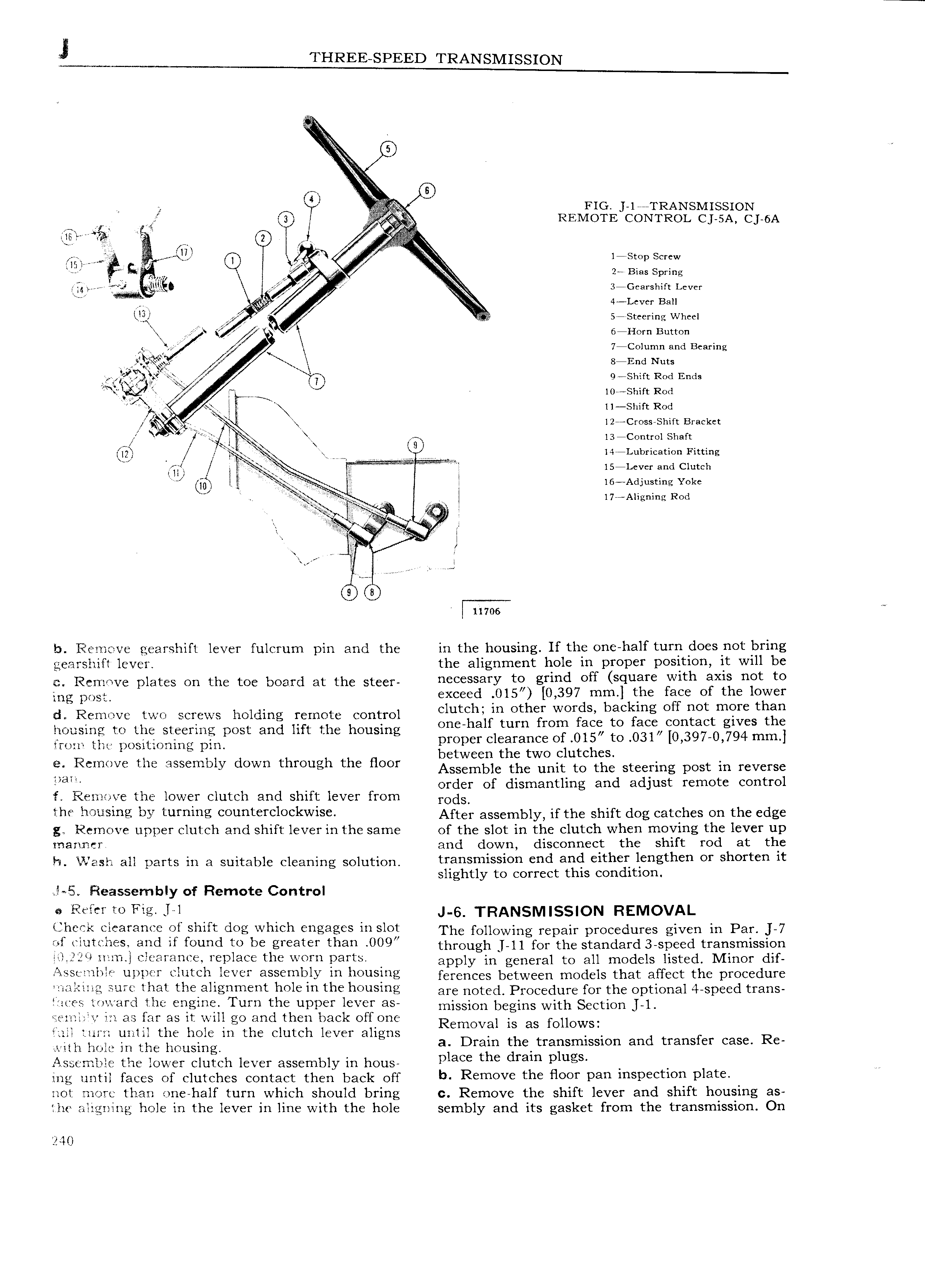
j THREE SPEED TRANSMISSION e FIG l I RANSMISSION ef df Gl A W REMOTE CONTROL Cj 5A C 6A I E i rl t VV l Q 1 Stop Screw rl lll Q A rr re X M 2 Bias Spring fr vii j g 3 Gearshift Lever I rlrf I 4 Lcver Ball l l Q 4 r j r 3 3eeriig Wheel N orn utton he V 7 Column and Bearing s gfi g 8 End Nuts W n fn X o sm R C1 E ri 32 r rrs 7 Y it 0 n s ri iomshart Rod se l 11 smrt Rod l2e Cross Shift Bracket 5 l3 Control Shaft e e Hr I4 Lubrication Fitting i 5 i r r FQ 5 LcvCr and Clutch 60 r c r J l6 Adjusting Yoke J lee y i l l7 lAIignin Rod ie s I Q s 11106 b Remove gearshift lever fulcrum pin and the in the housing If the one half turn does not bring gearshift lever the alignment hole in proper position it will be e Remove plates on the toe board at the steer 3YY tg grind eff Square with axis not to mg rms exceed 015 0 397 mm the face of the lolwer id Remove two screws holding remote control Clutch m Other WOfdS backmg Off not mqc in one half turn from face to face contact gives t e hoasing to thc steering post and lift the housing 0 1 O 397 0 794 mm gwrrr rh r r SrrrO rrng pim proper clearance of 015 to 3 i J between the two clutches e Remove the assembly down through the floor Assemble the unit to the Sreerrrrg pest rn reverse naw order of dismantling and adjust remote control f Remove the lower clutch and shift lever from rOdS the housing by turning counterclockwise After assembly if the shift dog catches on the edge g Remove upper clutch and shift lever in the same of the slot in the clutch when moving the lever up manner and down disconnect the shift rod at the ln Vlash all parts in a suitable cleaning solution t 3 m1 l0 end ann Cltncn lengthen OY Snoften It slightly to correct this condition l 5 Fieassembly of Remote Control Refer to Fig l l J 6 TRANSMISSION REMOVAL ijlieclt clearance of shift dog which engages in slot Thg fenewing repair procedures given in Par J 7 of clutches and if found to be greater than 009 thrgugh ii for the standard 3 speed transmission q f2 JQ iizini clearance replace the worn parts appiy in general to all models listed Minor dif xssl nlwlc upper clutch lever assembly in housing ferenees between models that affect the procedure irialziiry sure that the alignment hole in the housing are nO g5d Procedure for the optional 4 speed trans eces toward the engine Turn the uppef lever 35 mission begins with S CtlOU l l in far as it will g0 wid l 1 back Off One Removal is as foll0WS full turn until the hole lI1 il 1 clutch lever aligns D th t nd transfef C3S R wilh hole in the liousing ai rain d er rarismission a Assemble the lower clutch lever assembly in hous p ece t C mm p ugS ing until faces of clutches contact then baek Off b Remove the floor pan inspection plate not more than one half turn which should bring c Remove the shift lever and shift housing as ihe aligning hole in the lever inline with the hole sembly and its gasket from the transmission On 240