Ford Parts Wiki | GM Parts Wiki
Home | Search | Browse
Prev

 Next
Next
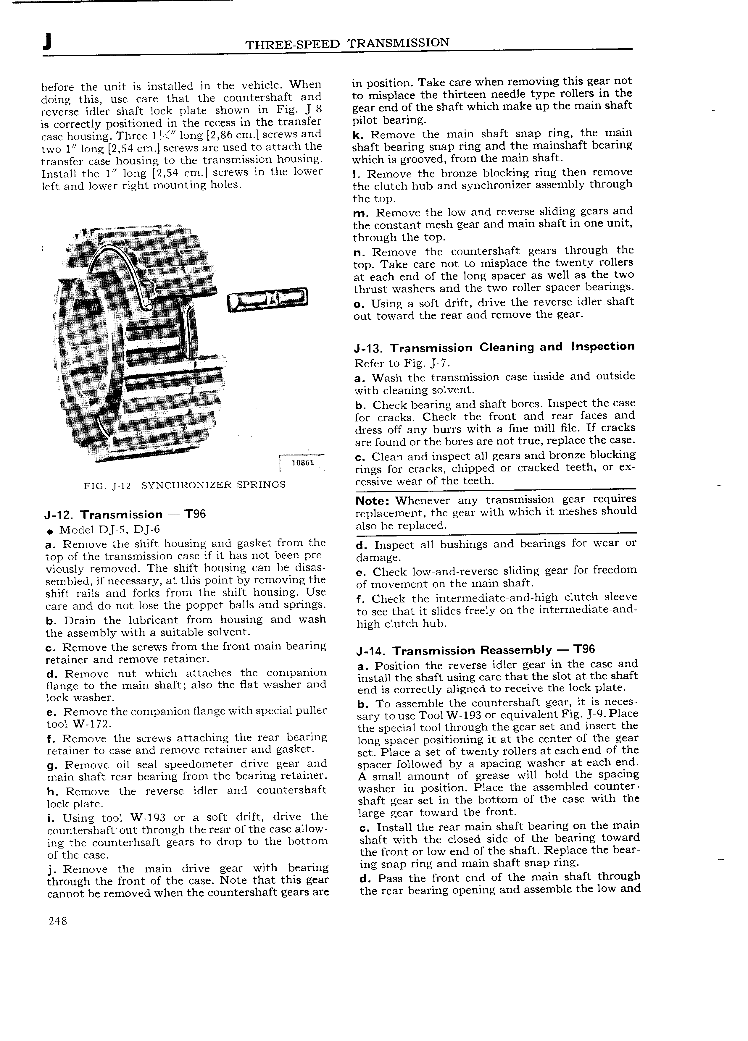
J THREE SPEED TRANSMISSION before the unit is installed in the vehicle When in position Take care when removing this gear not doing this use care that the countershaft and to misplace the thirteen needle type rollers in the reverse idler shaft lock plate shown in Fig 8 gear end of the shaft which make up the main shaft is correctly positioned in the recess in the transfer pilot bearing 6 housing Thr U so lO g 2 86 Cm Screws and k Remove the main shaft snap ring the main two 1 l0 g 2 54 Cm Screws M6 used to 3 t3 h rh shaft bearing snap ring and the mainshaft bearing transfer case housing to the transmission housing which is gyggvgd from the main Shafp fnstnff the fo long 2 54 ont sofows In tho fowof I Remove the bronze blocking ring then remove left and fowor rfgnt mounting holes the clutch hub and synchronizer assembly through the top m Remove the low and reverse sliding gears and Z xtzr Zta E I i the constant mesh gear and main shaft in one unit if i thmugh the mp L V n Remove the countershaft gears through the i i iE it E top Take care not to misplace the twenty rollers gg V i at each end of the long spacer as well as the two V r r t hrust washers and the two roller spacer bearings ff H ji ir i f V V 0 Using 3 sgft drift dirive the relverse idler shaft t e gear Zz zai 5 out towar t e rear an remove F i i i l J 13 Tra missi 0 e i g and n i f J 7 a Wash the transmission case inside and outside with cleaning solvent y V b Check bearing and shaft bores Inspect the case for cracks Check the front and rear faces and it dress off any burrs with a fine mill file If cracks i i fi are found or the bores are not true replace the case w86l c Clean and inspect all gears and bronze blocking rings for cracks chipped or cracked teeth or ex FIG 12 sYNCHRON1ZER SPRINGS C SSiV Wear of the t h Note Whenever any transmission gear requires J I2 Transmission T96 re lacement the ear with which it meshes should D i g Ode 1 5 DJ 6 also be replaced a Romovo the Shirt housing and gasket from the d Inspect all bushings and bearings for wear or top of the transmission case if it has not been pre damagg Vwusly romovod The Solo hoilsmg can bo dlSoS e Check low and reverse sliding gear for freedom sembled if necessary at this point by removing the of movement on the main shaft shift rails and forks from the shift housing Use d h h I h 1 care and do not lose the poppet balls and springs f Check too lotormodlatooo 1g C ut S oovo to see that it slides freely on the intermediate and b Drain the lubricant from housing and wash hi h dutch hub the assembly with a suitable solvent g c Remove the screws from the front main bearing retainer and remove retainen 1 T 3 i SSl0 Re Semb y t 96 d d Remove nut which attaches the companion OSI loo o foooroo 1 or goof m o oooo oo Hang to the main Shaft also the Hat Washer and install the shaft using care that the slot at the shaft end is correctly aligned to receive the lock plate lock washer b T bl th t h ft t o assem e e coun ers a gear i is neces f ioogloogg foo oomoomoo ooogo wooo ooooloo oooof sary to use Tool W 193 or equivalent Fig J 9 Place the special tool through the gear set and insert the f Romovo tho Scfows ottoohmg the roof ooooog long spacer positioning it at the center of the gear rotomor to Cooo and remove rstnrnsr ond goskoo set Place a set of twenty rollers at each end of the 9 R moV on Ser 1 Sr e d eter drrY g 3r and spacer followed by a spacing washer at each end mam shaft rear bearing from the bearing retainer A smalramgune Of grease will hold the spacing h Remove the reverse idler and countershaft washer in position Place the assembled counter lock late shaft gear set in the bottom of the case with the P i Using tool W 193 or a soft drift drive the fargo scar toward the front countershaft out through the rear of the case allow c Install the rear main shaft bearing on the main ing the counterhsaft gears to drop to the bottom shaft with the closed side of the bearing toward of the case the front or low end of the shaft Replace the bear j Remove the main drive gear with bearing ing snap ring and main Shaft snap rrng through the front of the case Note that this gear d Pass the front end of the main shaft through cannot be removed when the countershaft gears are the rear bearing opening and assemble the low and 248

 Next
Next