Ford Parts Wiki | GM Parts Wiki
Home | Search | Browse | Marketplace | Messages | FAQ | Guest
Prev

 Next
Next
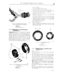
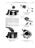
THREE SPEED TRANSIVIISSION J l9 TRANSMISSION REASSEIVIBLY T14A W I V Y V L V Note Lubricate all internal transmission parts before assembly using the proper lubricant V sr a Position reverse idler gear with Arbor Tool Vr We N 536 roller hearings and thrust washers in the l I II case Install reverse idler shaft forcing out Tool Vj i A W 336 Make certain the slot end of the idler shaft A is correctly aligned to receive the lockplate Refer i ii l l l r l r I V Q i i i i V r Q Y r r 4 V Q5 j l i i I wml l l r r re I t l I l r t l r EE l Y ixrl e l r l 3 I l ll V l llr l rrl r l i V 5 e i l ri V i i 2 r it agp r nZr l i r t e i i i I I rrili r r l f a V Y E i ii I r i ir Vi l r lr i V iiZ V e 1 g x I 12877 0 0 6 rio were counrensnprrr onlin Imi BEARING ARBOR rio 5 2 1 ocKrLArE 1NsrALLArioN lf LZ lif Z fi t 3 Arbor Tool W 335 3 i OunI rshHf t b Assemble the countergear center spacer four bearing spacers and countershaft bearing rollers gear shaft Press shaft through the gear hub as in the countershaft gear hub assembly as follows sembly and into the front of the case forcing out using Arbor Tool W 3 55 Place the center spacer Tool W 335 inside the hub and insert Arbor Tool in the spacer c Lgcgtg the lcckplatc in the slcts cf the reverse Pl 2 bwflng SP3 T at 3 h Gnd OY th Y 1 idler shaft and countershaft Tap the two shafts Spacer and lead a Set of beanng rvllcrs and r 1a alternately until lockplate is tight against ease a bearing spacer at each end to complete the as Refer tc Fig Q3 S IIIIIlY RGIIQI to FII I26 and I 27 e When assembling the mainshaft first install vs Install large countergear thrust washer in the nqajnsnnft low gggly and bronze blocking ring ln front of the case Position small thrust washer on stall hc lcw synclircnlzer assembly then install the countershaft gear hub with lip facing groove in the Sglgcf nt snap ring Refer to Fig 23 the case Holding the countershaft gear assembly in position start the countershaft in the rear of the N t IVIPIIIISIIQIPI Snap Img are S I CI Ht LG II case with the lockplate slot toward the rear and the IIIIIISIC CIIIICII hub and IIIQIII IIIIV bemmg slot in aligllment with the slot in the reverse idler end PI3Y Make Yt UU CON l U3D Ying 15 1 tdll d at assembly G 2 f Install the mainshaft second gear and bronze lf Y blocking ring Install the second third synchronizer rr V assembly then install select fit snap ring See g F Fig 22 yl X g Install reverse gear on mainshaft er V Vm R l h Install the mainshaft and gear assembly as a i 7 7 Y m T 4 r unit through the top cover opening of the trans l V mission case Refer to Fig l 18 T I Install bronze blocking ring onto the second t V r fj I fl third synchronizer assembly l P V j Install main drive gear roller bearings using low l X I N 6 G melting point grease to hold them in place Refer 4 QEH4 to Fig l 29 k Install the main drive gear and oil retainer I IG J 2 VOUNIERSHAFI BEARINGS washer slinger into the case with the cutaway AND SPACERS INSTALLED portion of the gear positioned downward toward gjjling Rouen the countergear assembly Guide main drive gear i u c rsh fr onto the mainshaft using care not to drop the roller QHCCFS slcmta Spacer bearings as shown in Fig J 30 254

 Next
Next