Ford Parts Wiki | GM Parts Wiki
Home | Search | Browse | Marketplace | Messages | FAQ | Guest
Prev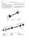
 Next
Next
A Ieep UNAYERSAL SERIESIIEELRJE ICE MANUAL C is 6 I4 W 5 7 g ig V A Q ii 1 gm sg pi Wi TIS F s 5 t Q i sg 5 14368 FIG jl 4 l 18 F C UR SPEED TRANsMlss1ic N MAINSHAFT Assizlvlnmr l Blocking Ring 8 Snap Ring 1 5 l3all 2 Direct and Third Clutch Sleeve 9vThrust Washer loeelaow and Second Clutch Hub 3 Sna p Ring 10 Second Speed Gtrar l 7 Retaining Ring 4 Spring ll Mainshaft 18 Low and Second Speed Gear Se Shiftxng Plate 4 12 Blocking Ring l9 Sec0nd Speed Synchronizer Assembly fx Direct and Third Clutch Huib 13 Shifting Plate 20 Direct and Third Synchronizer Assembly 7 Third Speed Gear Assembly 14 Poppet Spring J1 3 4 Speed Transmission Disassembly i Remove the oil slinger Refer to Fig l1 1 j Remove the snap ring from the outer bearing race of the transmiss n m insh ft t ll b Note The models T 98 and I 18 four speed ku VV l b li 3 8 hm arl n transmission are similar in design with exception of bl lltrlfa earmg pu C12 r mOV t C mams a t the second speed gear to mainshaft arrangement 1 mng In the model T 18 transmission the second speed m i gear is a slide fit on the mainshaft whereas in the Nfitef 1 Say l C S ry Fzdryihthe memgheft model T 98 transmission roller bearings and a firm aff y S l mg 6 cn O F mam nvc gear with a lead hammer to get sufficient clearance spacer are required IH this area Reter to Figs Jl 3 and JL4 to install the beaiing puller plates gi cmgvg the tran3mis5iOiiiT Q5r cage l Slltl tl 1 dlI Zt ElH delChlI d ClLltCl l sleeve tO the adapter plate and gasket Remove the oil seal from rear third speed position fneparate the mamshaft the plate and if damaged discard the seal assetrnbly from the main drive gear Be careful b Remove the transmission control housing as nm to lose any Of the mamshaft pilot beafmg sembly Refer to paragraph Jl 4 for its dis m U S assembly rrll Lift the mainshaft assembly out of the top c To make certain the two blocking rings direct of lihli Uansmlsslon Cas and third clutch hub and direct and thircl clutch n Remove the main drive gear from the trans sleeve will be assembled in their original relation mission case Shia mark them with 3 quick drymg laCql1 Sr OY an 0 Remove the miainshaft bearing rollers from the electric pencil Also mark the blocking ring low gem and second clutch hub and the low and second V U Speed gcan p Marls relationship between synchronizer hubs d Slide the low and second speed gear toward ami Fm splines On the mamlshaftf the new Of the transmission cass q Elegirl disassembly of the main shaft assembly e Disengage the reverse shifting arm and reverse b 1lr1j g tg mflp rmg wlglch lmhds th dgrefit shifting shoe from the reverse idler gear Remove am tm Sync mmzcr asscfm On t mains a the arm from the reverse shifting arrn pivot I Remove the front blocking ring from the front f Move the low and second speed gear into neutral Of the Shaft position s 1EE lide the direct and third synchronizer assembly g Remove the bearing retainer and gasket ami the third Speed gear assemblyr off the mam Remove 1 he snap rings from the main drive gear Shelf r d the outsr race of the bali t e r r s t Remove the snap ring at the rear or the mam h With a bearing uller remove the main drive shaft Slide the second synchronizer assembl and p Y gear ball bearing the blocking ring off the mainshaft 261