Ford Parts Wiki | GM Parts Wiki
Home | Search | Browse | Marketplace | Messages | FAQ | Guest
Prev

 Next
Next
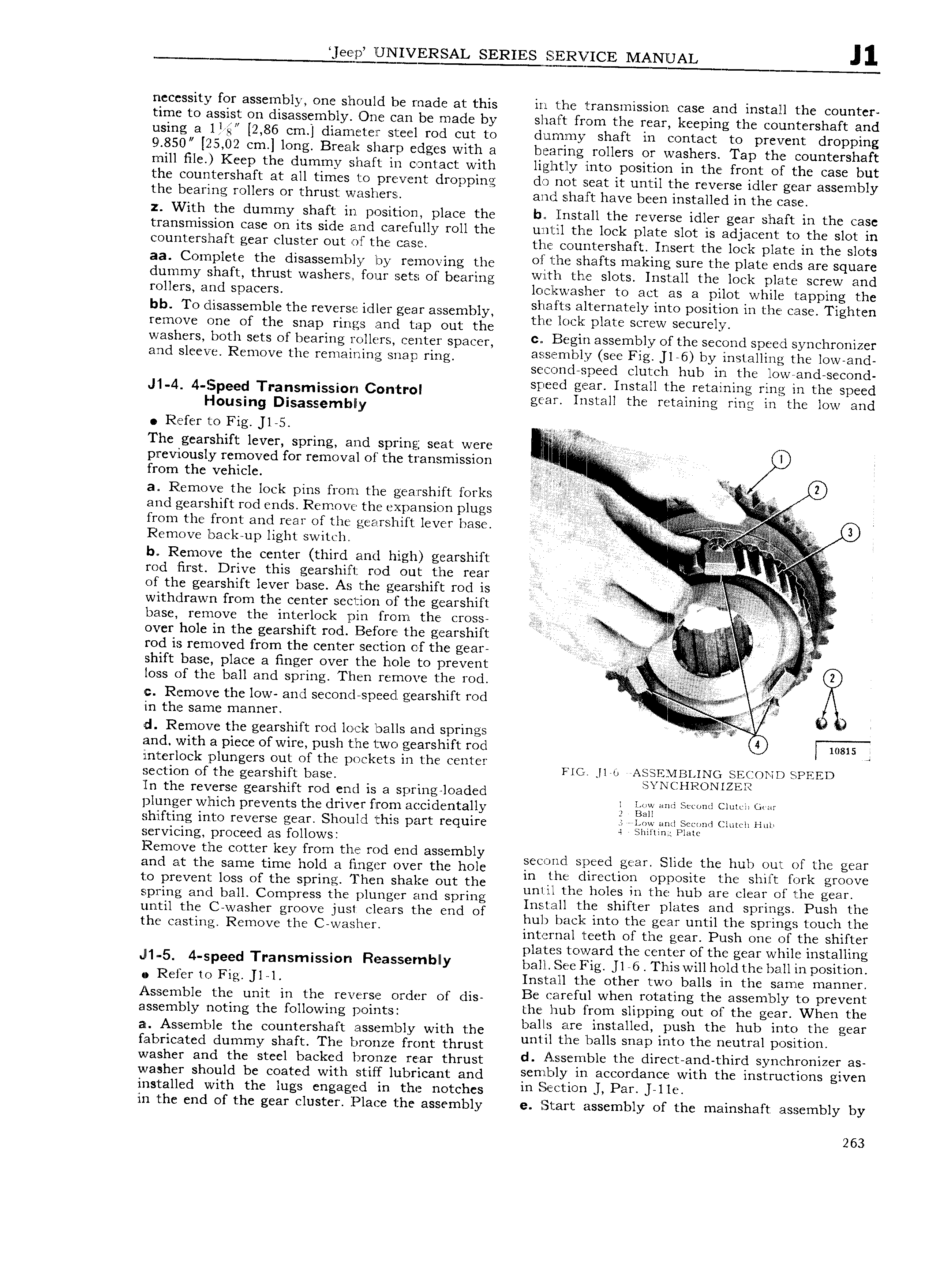
ee p UNIVERSAL SERIES SERVICE MANUAL necessity for assembly one should be made at this in the transmission case and install the counter time to assi st on disassembly One can be made by shaft from the rear keeping the countershaft and using a 1 gr 2 86 cm diameter steel rod cut to dummy shaft in contact to prevent dropping 9 50 25 02 cm long Break sharp edges with a bearing rollers or washers Tap the countershaft mill File Keep the dummy shaft in contact with lightly into position in the front o f the case but the countershaft at all times to prevent dropping do not seat it until the reverse idler gear assembly the bearing rollers or thrust washers and shaft have been installed in the case z With the dummy shaft in position place the b Install the reverse idler gear shaft in the case transmission case on its side and carefully roll the until the lock plate slot is adjacent to the slot in countershaft gear cluster out of the case the countershaft Insert the lock plate in the slots aa Complete the disassembly by remgving the Oil lille shafts making sure the plate ends are square dummy shaft thrust washers rem sets Or bearing v l FVl i this Sl tS lwall the l k r l it Screw and mucysy and spacers oczlcwasner to act as a pilot while tapping the bb TO disassemblc the YCVGTSH idler gear assembly shaftssalternately into position in the case Tighten remove one of the snap rings and tap out the the lOCl plate SCTEW Securely washers both sets of bearing rollers center spacer c B glh 3 1 hhlZV of the QhCl SDf il y Ch1 0 1Z 1 and sleeve Remove the remaining snap ring 3 h hlZ S Fig J1 6 by lh l3lhh thi lOWr3hd second speed clutch hub in the lowVand second J 1 4 4 pced Transrnissiow Control speed gear Install the retaining ring in the speed Housing Disassemblw gear Install the retaining ring in the low and Refer to Fig 1 5 my The gearshift lever spring and spring seat were previously removed for removal of the transmission 1 s from the vehicle V l W 3 2 a Remove the lock pins from the gearshift forks yi r j ii yi and gearshif t rod ends Remove the expansion plugs L r V i from the front and rear of the gearshift lever base I A i s i i L i l T g V 9 4 Remove back up light Switclli i i iiiiii e l V b R mO V thfb CCI1tCr third and high gggrghift rod first Drive this gearshift rod out the rear E l V Q of the gearshift lever base As the gearshif t rod is f V i ii f Z withdrawn from the center section of the gearshift r A W i esl base remove the interlock pin from the cross so 4 lA V over hole in the gearshift rod Before the gearshift A rod is removed from the center section of the gear t er s s gi A f s shift base place a finger over the hole to prevent ii loss of the ball and spring Then remove the rod A e Q c Remove the low and second speed gearshift rod V f Y in the same manner iiii l if i d Remove the gearshift rod lock balls and springs i and with a piece of wire push the two gearshift rod mais J interlock jplungers out of the pockets in the center F A W VD QPFFD Section of the gearshift base l J ll U 4 ln the reverse gearshift rod end is a spring loaded 4 U plunger which prevents the driver from accidentally g gx b l Shlftillg iU lZO I V I S gear ShOl lld this part require 5 rr lynw and Second Clutch Huh servicing proceed as follows 4 Bimini PMC Remove the cotter key from the rod end assembly V and at the same time hold a finger over the hole is U mQdf li d g U Sid ther hub Qul gf the gwr A in the direction opposite the shift fork groove to prevent loss of the spring 1 hen shake out the A Y 1 b H C m the Hun wr rmd S rin until the holes in the hub are clear of the gear p l ng am 3 O press le Y p g Install the shifter plates and springs Push the until the C washer groove Just clears the end of h lk k h 1 h h 1 the castinp Remove the C Wa rs l MT mi tfelgear unt tle spiir1 t Ou4 h q interria teet o tue gear us one o e s 1 er plaites toward the center of the gear while installing l1 5 4 speed Tr sm sS r Reaslsernblly bai1l s e1 ag ns riiiSWr11hOidther g 1impesison 0 Refer to Fig l l Install the other two balls in the same manner Assemble the unit in the reverse order of dis B6 Y h1lWh F f 3t1 g the SSem bly tO PY V ht assembly listing the fO11OWi g psimtis the hub from slipping out of the gear When the al Assemble the countershaft assembly with the bail m bH taH d p 1Sl hth htubl 1rltQt th gear habricated dummy shaft The bronze front thrust un Je 3 S Snap m O C neu re DOSI IO washer and the steel backed brotnze rear thrust d A hbl th hY Ct hd thlY l YhChifOh1Z 35 washer should be coated with stiff lubricant and h ll l Yl lh accofdahch with the lhstrhlctwhs gwch installed with the lugs engaged in the notches ih l UOh l Pai l ll in the end of the gear cluster Place the assembly e Start assembly of the mainshaft assembly by 263

 Next
Next