Ford Parts Wiki | GM Parts Wiki
Home | Search | Browse | Marketplace | Messages | FAQ | Guest
Prev

 Next
Next
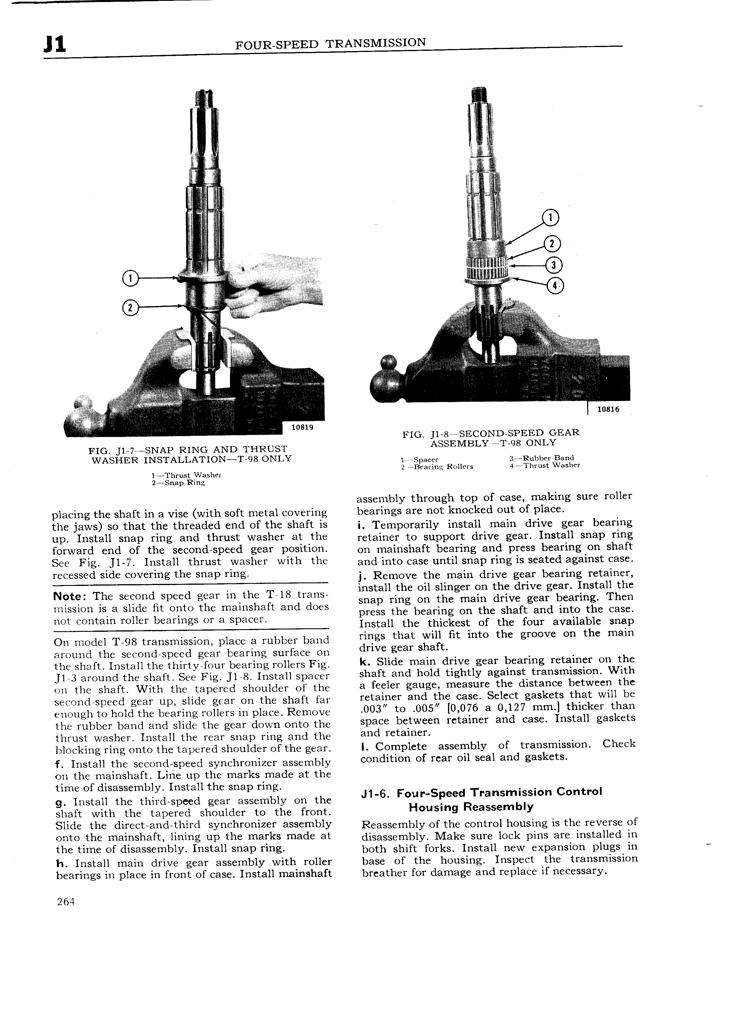
A 5w V A I 0 6 e lnqnvqnwq A it I ite I I I v Vq ql4 i E E i E A E E A I V AV E e I A 3 I mam FIG J1 8 SECOND SPEED GEAR FIG 1 7e SNAP RING AND ernizusr ASSEMBLYRTQS ONLY WASHER INs I ALLATIoN T 98 ONLY Vspacs Balsubbcr Band 1 Thrust Washcx 2 Bearing Rollers 4 1 hrust Washer 2 Snap Ring assembly through top of case making sure roller placing the shaft in a vise with soft metal covering bearings are not knocked out of place th6 jaws 0 that th6 thr68d6d 6hd Of th6 shaft is i Temporarily install main drive gear bearing UD Ihstah shap ring and thrust Wash6i at th6 retainer to support drive gear Install snap ring r0rWar l 6hd Ot th6 s660hd sP66d g6aY Q0s1t10h on mainshaft bearing and press bearing on shaft S66 Fhg J1 7 Install thrust Yl 3sh6F wlth th6 and into case until snap ring is seated against case reeeeeed elde Covstmg the snap tmg j Remove the main drive gear bearing retainer e e The eeeehe eeeee eeeh hehe The hehe 2 J 21 il g 3 E vZ 22 E a E mission 1S a slide fit onto the mainshaft and does TCSS the bcafm On the Shaft and into the Case mst Contain must bearings Or 3 Spaces ifnstall the thiciest of the four available snap On model T 98 transmission place a rubber band mags that Wm st mw the groove On the mam around the secondrspeed gear bearing surface on dtwsgcar ehefe the shaft Install the thirty four bearing rollers Fig k Sha 6 mam dr1V6 g6ar t 6armg retamfsr Oh the l 3 around the shaft See Fig l 8 Install spacer shaft and hold tightly agamst r em eS1 With on the shaft With the tapered shoulder of the a feelcr gauge measure the drstancs bctwcsra the secondspeed gear up slide gear on the shaft far r6tarrr6r and t h6 Casa Sclcct gaskets that Wm he enough to hold the bearing rollers in place Remove 003 to 005 0 076 a 0 127 mm l thrcker than the Ieubbgy band and Slide gear down Onto the sp3C bC tWC n I Ct81H 1 and CESC Install gaskets thrust washer Install the rear snap ring and the and r tam r blocking ring onto the tapered shoulder of the gear I Complete assembly of transmission Check f Install the second speed synchronizer assembly Csndrtttm ef rcar 011 scat and gaskets on the mainshaft Line up the marks made at the time of disassembly Install the snap ring T C t I g Install the third speed gear assembly on the J1 6 Foul Speed ransmlsslon on ro shaft with the tapered shoulder to the front H usm9 R assamb Y Shd6 th6 drrscteahaetthra sYh6hrOmZ6r ass6mblY Reassembly of the control housing is the reverse of OhtO th6 marrhshatt hhlhg UP the marks m8d6 at disassembly Make sure lock pins are installed in th6 tlm6 Ot drsass6rrrb1Y rhstah Snap rmg both shift forks Install new expansion plugs in ee h Install main drive gear assembly with roller base of the housing Inspect the transmission bearings in place in front of case Install mainshaft breather for damage and replace if necessary 264

 Next
Next