Ford Parts Wiki | GM Parts Wiki
Home | Search | Browse
Prev

 Next
Next
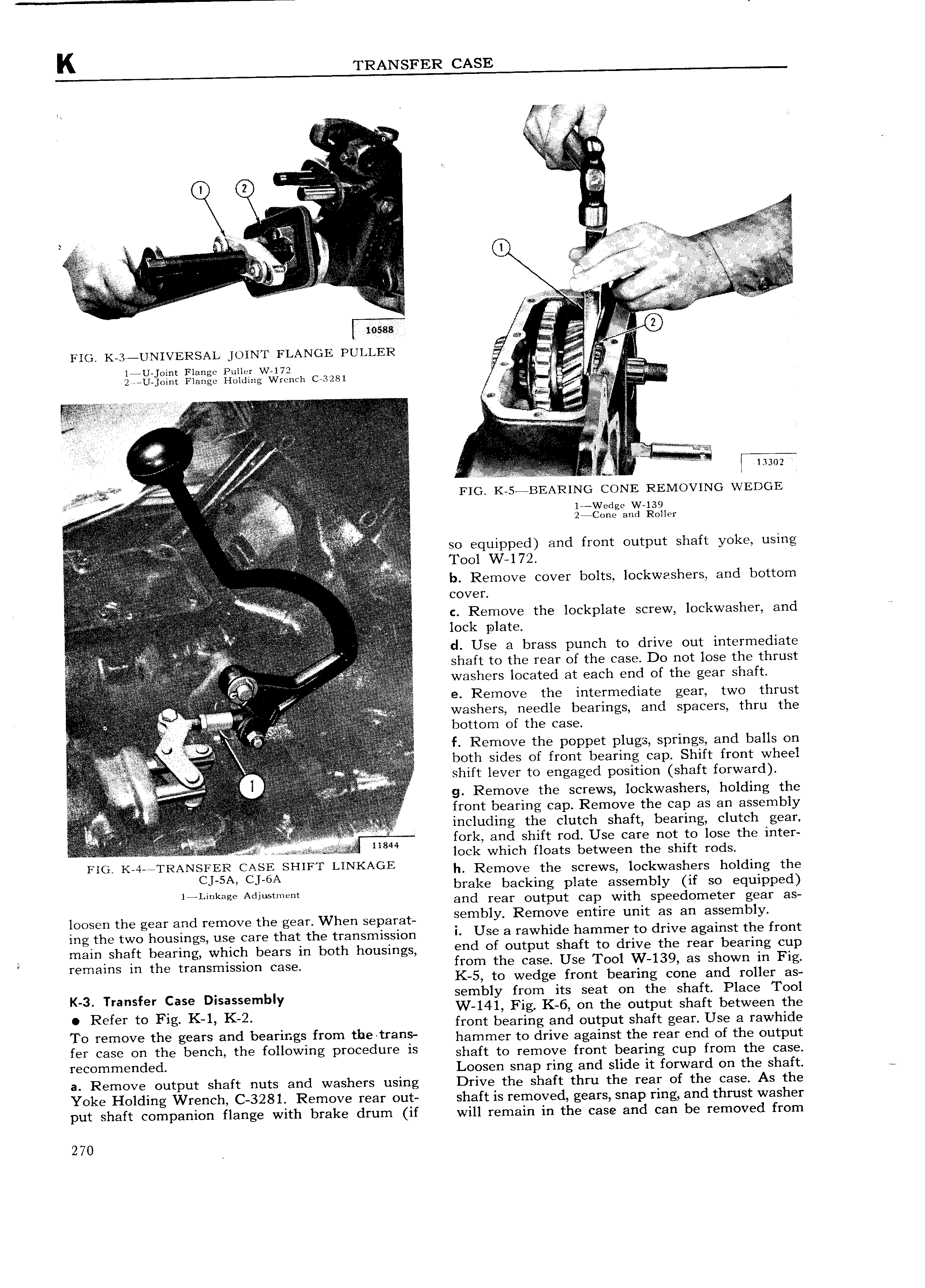
V zvv E z si V L V s G LV Q Q s iw A A V Q L A A EEEE 4 A z Q V VV 0 M V VVVVV I2 i V V QLQQQ 3 QQ L 4 s A A M VE i L z V VV s U t I VVV ZA E 3 LL V V V v V4 LL V A V i s A E E V A L rn xg wg g V i 0 rio K 3 UNIVERSAL 1o1N r ELANGE PULLER s LL Q2 EE E EE 14U Joint Flange Puller W 172 V LL 2v 2 V U joint Flange Holding Wrench C 3281 ss rilzn i L L L vi VVVVVV L LL L E 7 i 3 LQ L 1 L iE L r zz I 3 3 L as s L vV v QI L 1 I vL L L 5 E cr V LV 3 LL L Q Ti 3 LVL LVLL 3 A LQ LL L V 3 L L l V E Li V i si l rv ii I VL L I l t R M i p 13302 vV L L V FIG K 5 BEAR1NG CONE REMOVING WEDGE 3Q L L L LL Q L L i EV E Q L L L eas V L Q QLQLLj L L E Q L Q Y QLVQ f Q V LQLL LQQ5 T QL V L A Q V V v L QQ V L L L V L gffgcarlg lsoaler L L QQ C QLiQ QL AQ LLLL L LL Q Q E LL QQ so e ui pecl and front out ut shaft y l e using 7 Z e i L T 1 7 p L Z L Lv 3 f 1 V VV LV L QQ L L V L V L VV V L V L E OO 2 LQQQQ T Q KLQ Q i QLLL LL L ls Rsmsvs ssvss lsslts lsskwsslssfsy sssl lssttsm VL Qi V V VL V VV V VL If LLLL E V VQ 5 VZ V ELLQQilifizgfrfili L VVVV V V Y si COVEL jjQfL L 3 LL e V A L L L Q L L sfj V isQJ jf grlj c Remove the lockplate screw lockwasher and L L QLVVLV VVVV V V LL iz L Q L 2 L V L 3i VLL L L l l r l t Q A Q gf i ZLLZ QV LL 33 rj VL V L L Q d Use a brass punch to drive out intermediate L L L t i Q r i L s r S L Q L QLL LAQQ slssft ts tlss tsss sf the ssss Ds mt lsss tlss thrust VVVL V Washers located at each end 0f the gear shaft Lv r V Q L V i V e Remove the intermediate gear two thrust 33 L f Zjz V Q V Q L LQf Q V L washers needle bearings and spacers thru the Qs Q L L iLVi t V CFL V LQi F bottom of the case L L L QLL rL it QQ r Y QY L iQ Qii i Q Z s Q L fft Q z 2 f Q g Q Ejlgg L f ij QLQ Q L f Remove the poppet plugs springs and balls on je z gg L L 2L L3 Q jf g L V g E L L I LV both sides of front bearing cap Shift front wheel Q V f L QQ e L Q rL shift lever to engaged position shaft forward V Q Q g Remove the screws lockwashers holding the QL r L 3 3 QQ L front bearing cap Remove the cap as an assembly 3 L LQQ t L QLL 3L L L Q st LLL 3 t i 2 Q QLiL Q L L L L l sl ll s ths Clutch slssft lsssflsa slstsh gsm QL LL Q L Q L t L i L Li E i Qi L L L Q i 1s i 8 fsfls ssd shift s l Uss Cass mt ts lsss tlis l tss Q s L L Q Q Q Q QQ L LQ Me e es s r s r2 ss L i lock which floats between tl 1 shift I Od FIG K 4 RAN 3ls r C ASHIFT LINKAGIL h Remove the screws lockwashers holding the I L k Ad brake backing plate assembly if so equipped T m age Jusmen and rear output cap with speedometer gear as loosen the gear and remove the gear When separat mbly Remgve sms umt as an assembly ing the two housings use care that the transmission Use 3 tawhlds h3mmOY tO dYlV agalnst ttls tYO t main shaft bearing which bears in both housings Oud of OutPut shaft tO dtlV the rear b 3Yltlg Cup t rsmnins in the transmission Cass from the case Use Tool W 139 as shown in Fig K 5 to wedge front bearing cone and roller as K 3 Transfer Case Disassembly sembly from ITS seat on the shaft Place Tool Refer to Fig K 1 K 2 W 141 Fig K 6 on the output shaft between the front bearing and output shaft gear Use a rawhide TO tOmOV the gsats and beatings ttOm thO tI 3Os hammer to drive against the rear end of the output fsf Cass Ou the b uCh ths tOllOWlOg PtOOOduYO ls shaft to remove front bearing cup from the case tswmmsudsd Loosen snap ring and slide it forward on the shaft a Remove output shaft nuts and washers using Drive the shaft thru the rear of the case As the Yoke Holding Wrench C 3281 Remove rear out shaft is removed gears snap ring and thrust washer put shaft companion flange with brake drum if will remain in the case and can be removed from 270

 Next
Next