Ford Parts Wiki | GM Parts Wiki
Home | Search | Browse
Prev

 Next
Next
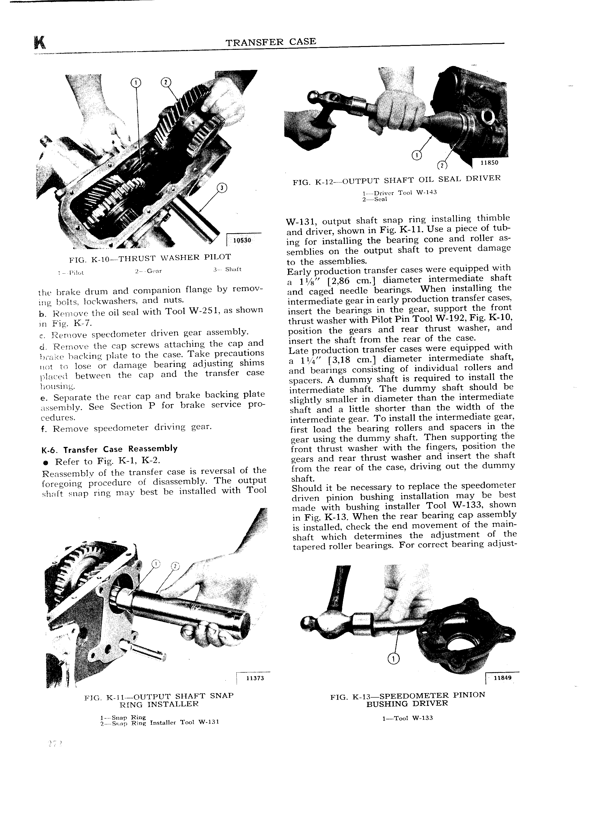
K TRANSFER CASE 0 6 E T l A i E i V E Tg 7 T i r S gg T rA g T T H V E V 2 V V E V I TT iEV E 1 g wai V E 1 V 4 V T 0 A f 2 11850 fg F T I 0 Fic K 12 OUTPUT sHAFT OIL sEAL DRIVER Ee ei 1 1 Driver Tool W 143 zeseai 1 T 1 Vi T A 5 V W 131 output shaft snap ring installing thimble and driver shown in Fig K 11 Use a piece of tub 5 V ws 0 at ing for installing the bearing cone and roller as FIG KAOWTHRUST WASHER PILOT semblies on the output shaft to prevent damage T y to the assemblies Te Wm to TGPM 3 T Sem Early production transfer cases were equipped with h I k d d fl x b a 11 g 2 86 cm diameter intermediate shaft T L Qi fl lem e Cofnzemofl enge y mmow and caged needle bearings When installing the M2 YM O i W i U S dl rm S intermediate gear in early pI OdL1CflOH tI 3f1Sf I C3S lu T Y2i Q tE true oil seal with Tool W 25l as shown insert the bearipgs in the gem Support the front m F li KV thrust washer with Pilot Pin Tool W 192 Fig K 10 Eiiemove speedometer driven gear assembly position the gears and rear thrust washer and ti Retrieve the cap screws attaching the cap and insert the shaft from the rear of the case lar rite backing plate to the case Take precautions LGTB PY0dU ti0 U8 f f CHSBS W Y 1 1PP d with not to lose or damage bearing adjusting shims 3 11 EH 3 18 Cm diameter i t fm di3t shaft i e i betgveen the gap and the transfer case and bearings consisting of individual rollers and l lroiising spacers A dummy shaft is required to install the ee Separate the rear cap and brake backing plate intermediate Sheff The dummY Shef Sh 1d b 1 assembly See Section P for brake service pro Shg tlY i1meuiY m dgemeter than the Wgefmedlete C jm S sha t an a ittle s orter than the wi th of the L R mOV Sp dOm t f driving gean intermediate gear To install the intermediate gear first load the bearing rollers and spacers in the gear using the dummy shaft Then supporting the K 6 Transfer ease Reassembly front thrust washer with the fingers position the R f Y tv Fig K 1 K 2 gears and rear thrust washer and insert the shaft Reassembly of the transfer case is reversal of the from the rear of the case driving out the dummy foregoinv procedure of disassembly The output shaft shaft snip ring may best be installed with Tool Should it be necessary to replace the speedometer driven pinion bushing installation may be best 4 made with bushing installer Tool W 133 shown in Fig K 13 When the rear bearing cap assembly is installed check the end movement of the main shaft which determines the adjustment of the V r T w e tapered roller bearings For correct bearing adjust TTT T lj Zh 1 Tr 1 q ig 5 j 1 5 s I 1 t 1 R t i s e T T TT i i T liii T i T i i r g T A r A r r Vf T p A I A giryywlh T HBV x V s T r 1 T t T Er T irli 1 1 irc 1 Z2 T Q T AT 1 r 1 E i S i 1 373 FIG K ll OUTPUT SHAFT SNAP T T FIG K l3 SPEEDOMETER PINION RTNG INSTALLER BUSHING DRIVER eiigiigg gig rnstaiier Tool W 3l 1 Tool W 133

 Next
Next