Ford Parts Wiki | GM Parts Wiki
Home | Search | Browse
Prev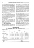
 Next
Next
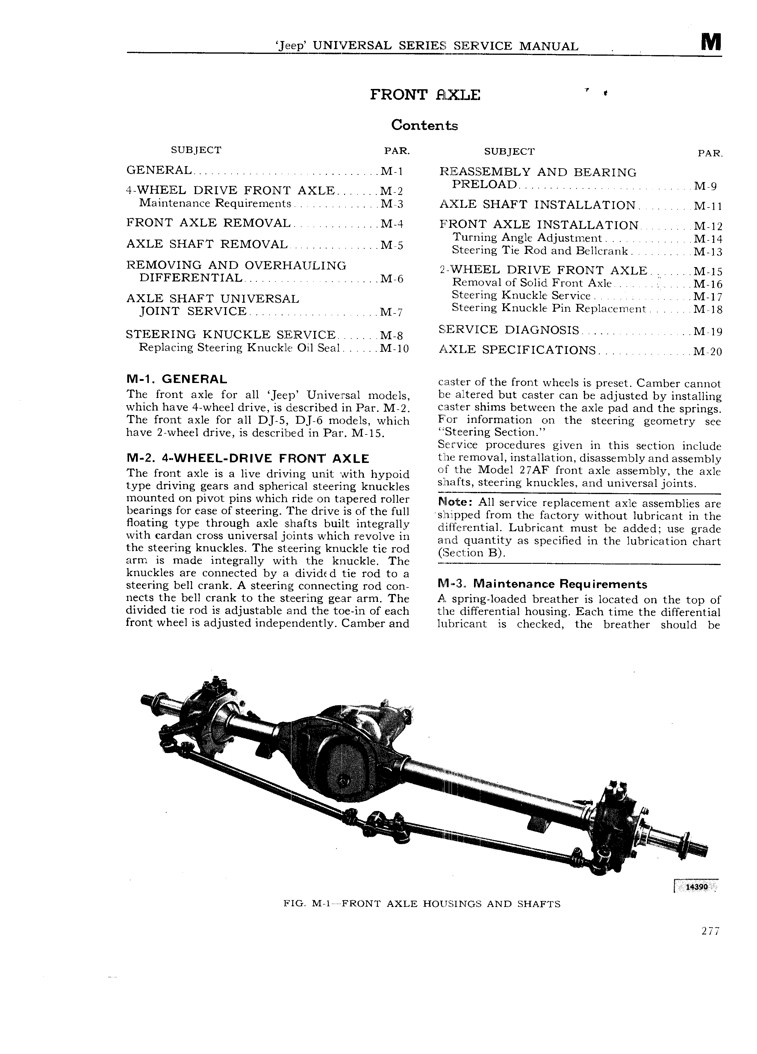
gep UNIVERSAL SERIEEQLEERVICE MQJUAL M FRONT Ell jX LE Contenizs SUBJECT PAR SUBJECT PAR GENERAL 44 E 4 M l Rl5 AS E EMBLY AND BEARING WVVHEEL DRIVE FRONT AXLE 4 Q M 2 IRELOAD 4 ATTT M 9 Maintenance Requirements M 3 AXIJE SHAFT INSTALLATION M ll FRONT AXLE REMOVAL M 4 lE RON I AXLE INSTALLATION M 12 T A l Ad l M AXLE SHAFT Renew TT 7 TTA Ma SELQEEEE Ti giiai E Ell aa I ive REMGVING AND OVERl lZAULlNG znw n1i EL DR1vE FRoNT AXLE M 15 DIFFERENTIAL r M 6 Removal of Solid Front Axle i M l6 A Steering Knuckle Service M 17 I AL 4 I g A 4 M 7 Steering Knuckle Pin Replacement M l8 STEERING KNUCKLE SERVICE lblhhnn M 8 SELERVICE DIAGNOSIS Mel9 Replacing Steering Knuckle Oil Seal M 10 AXIJE SPECIFICATIONS M 20 V 1 GENERAL ca 1 er of the front wheels is preset Camber cannot The mnt axle for 3 J g p Ijjqivegrggl mOd lS be altered but caster can be adjusted by installing which have 4 vvheel drive is described ih Par M 2 e a te j Slllms between the axle pad and the Springs The from axle for all D 5 Dj 6 models which Yfqf 1nl 0l mat1 n On the steering geometry see have 2 wheel drive is described in Par l I I5 te el lllg Seetl0ll Service procedures given in this section include M 2 4 WHEEL DR VE FRONT AXLE the removal installation disassembly and assembly I he front axle is a live driving unit with hypoid Olfltglc ll Iod l ZIZAF lgmlt MSIE aetiemlbllx th axle type driving gears and spherical steering knuckles g meuflted OU DlVOt Pills which tide OU tllpefed reller 1te All service replacement axle assemblies are beanngs fe ease af Steering The dYlVe ls at the full shipped from the factory without lubricant in the llaatlng type tlnangla axle alt afta benlt lntegrally dlirhaehaai LUbFlCi3Ht must be added use grade with cardan cross universal joints which revolve in and quantity as Specified in the jubr iCatiOn chart the steering knuckles The steering knuckle tie rod CC1 iOn B arm is made integrally with 1 he knuckle The t knuckles are connected by a divided tie rod to a I j steering bell crank A steering connecting rod con M Malntenance Requlremelnts nects the bell crank to the steering gear arm The A spring loaded breather is located on the top of divided tie rod is adjustable and the toe in of each the differential housing Each time the differential front wheel is adjusted independently Camber and lubricant is checked the breather should be tttii ij i A fl 3 i i i i i 4 A TQ Mp M E J ZQfE zjr 4 V a 1ii ir T ii l eice 143 tec e ee FIG M le FRONT AXLE HoLns 11 rGs AND SI IAFTS 277