Ford Parts Wiki | GM Parts Wiki
Home | Search | Browse | Marketplace | Messages | FAQ | Guest
Prev

 Next
Next
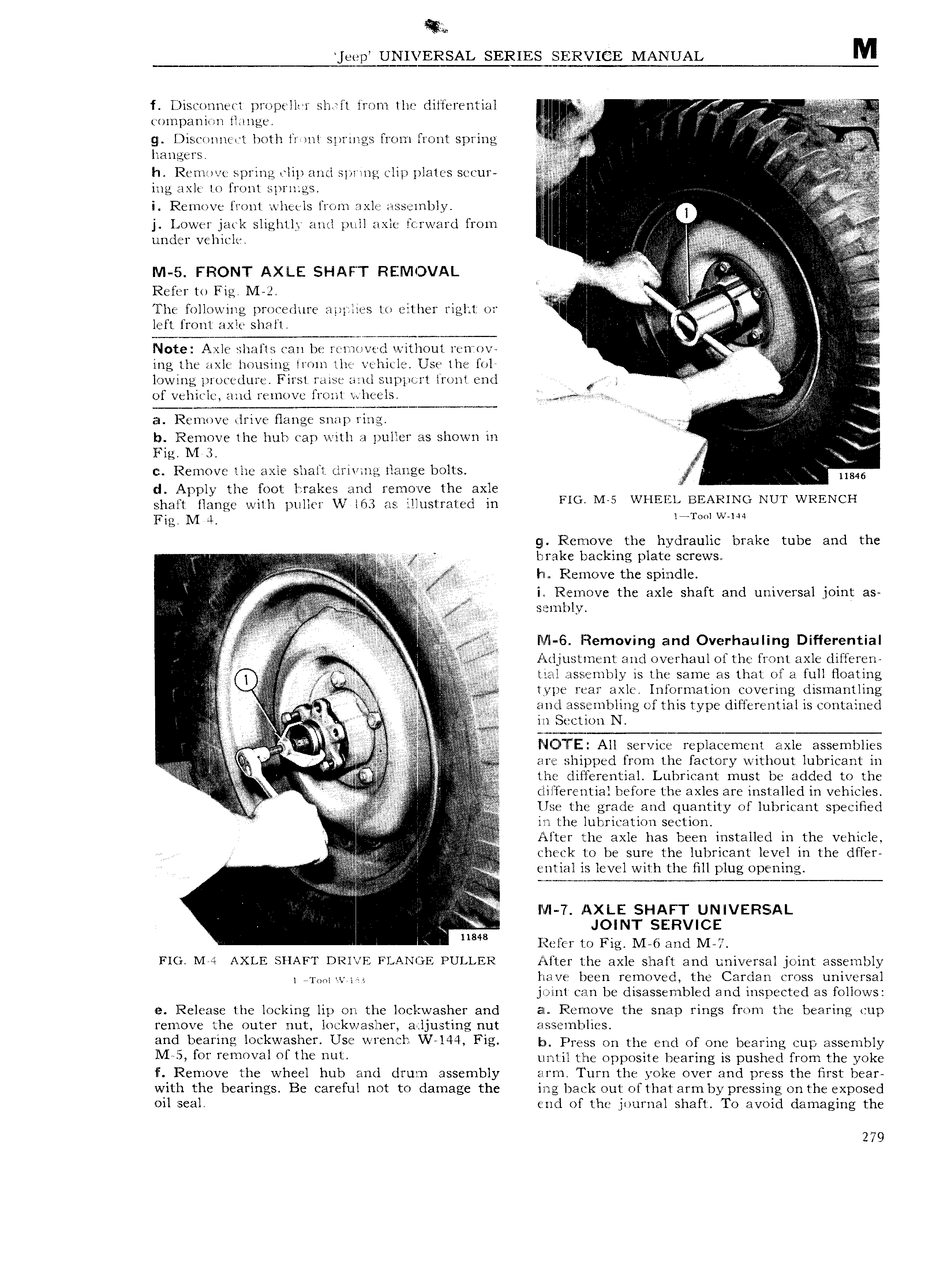
eep UNIVERSAL SERIES SERVICE MANUAL M f Diseoiinect propeller sbrft from the differential l U f V g L 1 compani in flange le ff N we fj L gi l isconnel t both livwnt springs from front spring h Reninve spring clip and spriiig clip plates se Jur A ii ing axle to front springs QZ l c i A 2 I Remove front wlieels from axle assembly i V V 0 l t t t t J Lower Jack sllghtlj and pull axle tCi N 1t l f1 O1U l i J 5 Z i all under vehicle i V l T ee 2 V IVI 5 FRONT AX LE SHAF l REMOVAL r e tntt t t Refer te Fis M ze Y i e t i lfhe following procedure applies to either right or I i i 2 E r ae e5 left front axle shaft l i i f 1 2 i Note Axle shafts can be l i 1 J t Zl without 1 C tT V e are i I 1 Q ing the axle housing from the vehicle Use the fol I lowing procedure First raise antl suppcrt front end gi V v of veliiele and remove front it heels e M an Remove tirive flange SNMP l lUz i N F lfz I b Remove the hub cap with puller as shown in W Fig NI 3 V if f in c Remove the axle shaft tlrivang flange bolts V 11846 d Apply the foot brakes and remove the axle F V shaft flange with puller VV l63 as illustrated in Flu M WHEILL BEARING NUT WRENCH Ifig M Ll l Tool VV N4 gp Rlernove the hydraulic brake tube and the biiakc backing plate SCTCWSH e Q fl F v the r i dl e V l l R N i Remove the axle shaft and universal joint as j t tr A itti f i ii1 fe B j etl gag 3 e y gg seef Ml 6 Removing and Overhaulmg Differential iii l Q M Adjustinent and overhaul of the front axle differen c f ei a jN M tra assembly is the same as that of full Heating T type rear axle Information covering dlsinafltllng 1 1 tt J je 1 3 gag Q a nd assembling of this type differential is contained 2 we r I i in t N ee e Te f R I i e M 2 j V 2 4 A ll I I4C l ll E All service replacement axle assemblies 4 e elle gihipped from the factory without lubricant in A V i the differential Lubricant must be added to the V t azzyy it t lil l e rential before the axles are installed in vehicles e zu i Q f Use the grade and quantity of lubricant specified A gp V E in l he lubrication Sec ti0 E i i i E V After the axle has been installed in the vehicle A check to be sure the lubricant level in the dffer V emial is level with the fill plug opening i I I A i i r t g ii 7 Axu SHAFT UNIVERSLAL gg JOINT SERVICE A 11848 E lefer to Fig M 6 and M 7 Fio Me AXLE sr1AFr nerve Fmlnoe r u1 1 1 R Alter the axle shaft and universal joint assembly I T Ol yc er have been removed the Cardan cross universal joint can be disassembled and inspected as follows e Release the locking lip on the lockwasher and an Filemove the snap rings from the bearing cup remove the outer nut loekwasher adjusting nut assemblies and bearing lockwasher Use wrench W 144 Ftg I Press on the end of one bearing cup assembly lVI i OY T mOV3l Ol UW ULW uritil the opposite bearing is pushed from the yoke IF Remove the wheel hub and drum assembly arm Turn the yoke over and press the first bear with the bearings Be careful not to damage the ing back out ofthat arm by pressing on the exposed oil seal end of the journal shaft To avoid damaging the 279

 Next
Next