Ford Parts Wiki | GM Parts Wiki
Home | Search | Browse | Marketplace | Messages | FAQ | Guest
Prev

 Next
Next
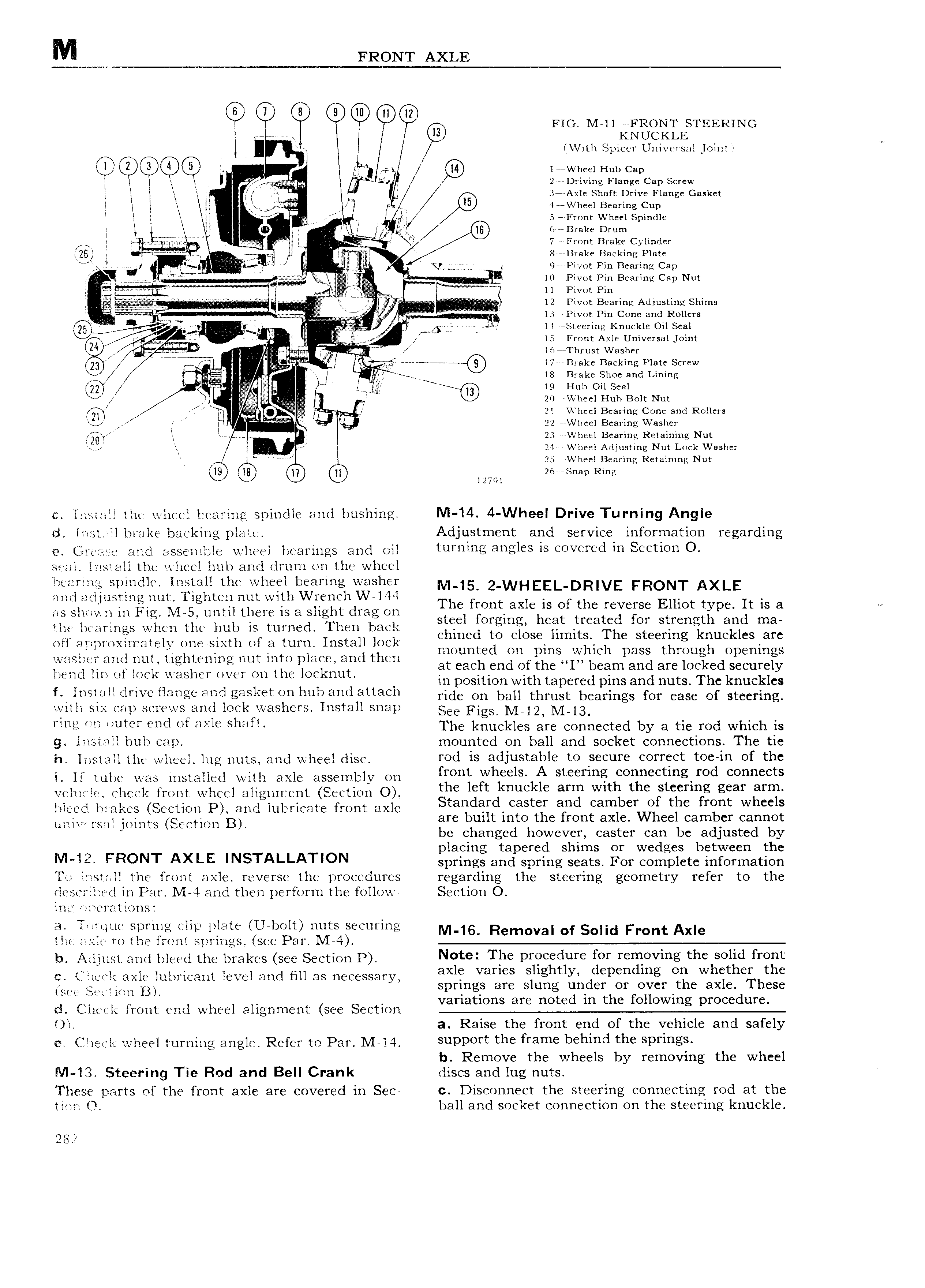
M M FRONT AXLE 6 Y R Q ll l2 L FIG M ll FRONT STEERING I V KNUCKLE I t I V1th Spicer Universal joint fw 1 V kl ai I r Wheel Hub Cap t l I Q 2 rDriving Flange Cap Screw l l It l X v i 37 Axlc Shaft Drive Flange Gasket l t rl i r 47 VVl1eel Bearing Cup t r aj it M 5 Front Wheel Spindle t g t t ti ri 6 Brake Drum 1 ti zugmi nw I V 1 I J 7 Front Brake Cylinder CZBB I F AI I I t i t 8 B1 ako Biarking Plate JY I t Ii 1 I r M t We Pivot Pin Bearing Cap M M 2 l0 rPivot Pin Bearing Cap Nut 1 1 tt 1 1 1 1 1 1 1 1 1 11 1 v 12 Pivot Homin Adjusting Shims kn 4 V H I I E I lli Pivot Pin Cone and Rollers jig t ty R v gist MIMI i s ll rsrccir1 c Knuckle Oil Seal N V rg 1 l k F yl l5 Front Axle Universal joint I Ti M I lfw l hrust Washer E5 M f Q I W V rr i l7 B1akc Backing Plate Screw I fly 18 Brake Shoe and Lining UI is Hoo oai scci ii it i 20 VI heel Huh Bolt Nut f I 2l VVheel Bearing Cone and Rollers A il I4 22 Wlieel Bearing Washer Mi It 4 i 23 VVheel Bearing Retaining Nut I 24 V heel Adjusting Nut Lock Washer l fd J ZS Vi heel Bearing Retaining Nut 49 18 ll zo snap Ring J 1z7 1 liistail the wheel hearing spindle and bushing Nl 14 4 Wheel Drive Turning Angle ci Inst il brake hacking plate Adjustment and service information regarding e i t a and asseiuble wheel bearings and oil Iumlmg 3 I 15 0V 1 d IU S TQ10 O sesai Install the wheel huh and drum on the wheel liearzng spindle Install the wheel bearing washer M 15 2 WHEEL DR VE FRONT AXLE and adjusting nut I 1ghten nut with Wrench W l44 Th front Xl f th Y EH t It as shown in Fig M 5 until there is a slight drag on C 3 IS O cvcrsc IO yp IS 8 i Y steel forging heat treated for strength and ma the hearings when the hub IS turned Then back Chmed tO Close limits Th t Yin kn kl S I off a proxirr ately one sixth of a turn Install lock 1 B S ee uc C 3 C KVNWT md nm ti rmx I d mounted on pins which pass through openings c c tiring nut into p ate an then 1 at each end of the I beam and are locked securely bend hn of lock washer over on the locknut in position with tapered pins and nuts The knuckles f II 1Sl lll drive flange and gasket on hub and attach tide On ban thrust beatings fm Case Of steering with six cap screws and lockfwashers Install snap SCC FigS Mij2 M l3 IIIIQI II IIIQI II I OI IIYIQ Sheri The knuckles are connected by a tie rod which is g liistall huh cap mounted on ball and socket connections The tie h install the wheel lug nuts and wheel disc YOd IS 3dlU t3bl to UY COYYQCI t0 1U of the i lf tube was installed with axle assembly on mnt Wh IS kA Steefmg Orm tmg rOd Ccmnccts veliiirht check front wheel alignxrent Section O ghc lgftd Huhlc ang Wlth the Ftcgrlzg gear SU bleed brakes Section P and lubricate front axlc tan QI Faster an Cambef O t C mnt W cc S tmtvt tm tmnts SC tiO B are built 1nto the front axle Wheel camber cannot be changed however caster can be adjusted by 4 G placing tapered shirns or wedges between the IVI FFICNT AXI E INSTALLATION springs and spring seats For complete information To install the front axle reverse the procedures regarding the steering geometry refer to the l scriltt d in Par I L4 and then perform the follow Section O illil 1 crations Eli T i t Llt Sprixrig clip plate Il l OlI HUICS S CUI lI ltQ M 16 Rernoval Of Front Axle that axle to the iront springs see Par M 4 li Atijoci and oiccci nic brakes ccc Section P N t T be prqcedurc f r r vmg the wild from i iilIn l C axle lubricant level and fill as necessary iggin agis 1IE 1Igd qdC p Id I3 gf iI Wa1 ith h21g see S t 1 ii B 6 C I at t d i th foll d cz coccic lront end Wiicci alignment see Section Ol a Raise the front end of the vehicle and safely rz Check wheel turning angle Refer to Par M l4 SUDPOII IIIC frame bchmd the SPIIIIES b Remove the wheels by removing the wheel Nl 13 Steering Tie Rod and Bell Crank discs and lug nuts These parts of the front axle are covered in Sec c Disconnect the steering connecting rod at the time O ball and socket connection on the steering knuckle 1282

 Next
Next