Ford Parts Wiki | GM Parts Wiki
Home | Search | Browse
Prev

 Next
Next
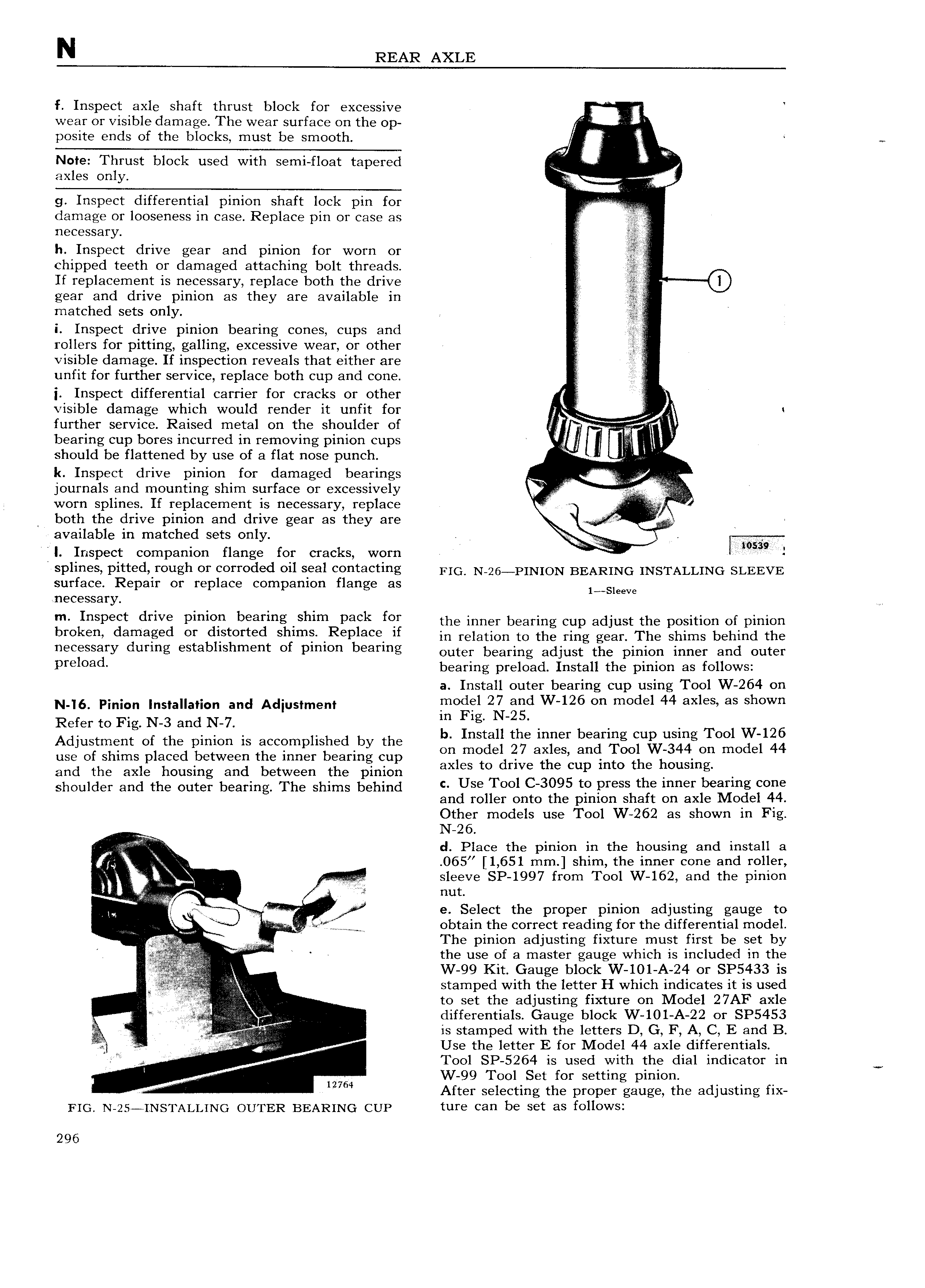
N REAR AXLE f Inspect axle shaft thrust block for excessive wear or visible damage The wear surface on the op V posite ends of the blocks must be smooth Note Thrust block used with semi float tapered td if axles only iii 4 g Inspect differential pinion shaft lock pin for v r E damage or looseness in case Replace pin or case as 4 necessary h Inspect drive gear and pinion for worn or chipped teeth or damaged attaching bolt threads If replacement is necessary replace both the drive 0 gear and drive pinion as they are available in matched sets only C isi i i Inspect drive pinion bearing cones cups and rollers for pitting galling excessive wear or other I visible damage If inspection reveals that either are QQ unfit for further service replace both cup and cone j Inspect differential carrier for cracks or other ii visible damage which would render it unfit for further service Raised metal on the shoulder of bearing cup bores incurred in removing pinion cups i 4 l should be flattened by use of a flat nose punch i k Inspect drive pinion for damaged bearings journals and mounting shim surface or excessively i iiii I worn splines If replacement is necessary replace ii r both the drive pinion and drive gear as they are Q l available in matched sets only V 4 W I Inspect companion flange for cracks worn I i Pli S Pi d Y0 gh f Cmmded eil Seal 0 t3 ti g rio N 26 1 1N1oN BEARING INSTALLING SLEEVE surface Repair or replace companion flange HS 1 Sleeve necessary m Inspect drive pinion bearing shim pack for the inner bearing cup adjust the position of pinion br k damaged ol dlstolled Slllllle Repleoe ll in relation to the ring gear The shims behind the necfssgry duflng St8bllSl 1fI 1 1 lt of pll llO l b 3l lUg Outgr bearing adjust the pi1 1iOn iI l1 l I Bild OUt l pre oa bearing preload Install the pinion as follows a Install outer bearing cup using Tool W 264 on N I6 Pinion Installation and Adjustment looogel 213 gd W l2o oll model 44 eXleS as Shown Refer to Fig N 3 and N 7 El Ilgg u th b Tool W 126 ns a e inner earing cup using Adiustmet Of the mon is acctmpllslwby the m model 27 ami Tool W 344 m model 44 use of shims placed between the 1nner bearing cup 1 t dri th C into the housin and the axle housing and between the pinion ax es O Ve 6 up g shoulder and the outer bearing The shims behind C Use Tool C 3o95 te press the lllllel oeallllg Colle and roller onto the pinion shaft on axle Model 44 Other models use Tool W 262 as shown in Fig A N 26 d Place the pinion in the housing and install 8 i 065 1 651 mm shim the inner cone and roller Q j 4 sleeve SP 1997 from Tool W 162 and the pinion A ri Via nut nw A iii g r gg e Select the properlpinion adjilsting gauge to 4 W l e j obtain the correct reading for the differential model A Ai I The inion adjusting fixture must first be set by l l 4 th p r 4 ir it 1 d C1 ui e use o a mas er gauge w ic is inc u e 1 e W 99 Kit Gauge block W 101 A 24 or SP5433 1S stamped with the letter H which indicates it is used to set the adjusting fixture on Model 27AF axle 4 t 1 jg i 4 l differentials Gauge block W 101 A 22 or SP5453 j g is stamped with the letters D G F A C E and B x V Use the letter E for Model 44 axle differentials 4 Tool SP 5264 is used with the dial indicator in I W 99 Tool Set for setting pinion 4 12764 After selecting the proper gauge the adjusting fix FIG N 25 I NSTALLING OUTER BEARING CUP ture can be set as follows 296

 Next
Next