Ford Parts Wiki | GM Parts Wiki
Home | Search | Browse
Prev

 Next
Next
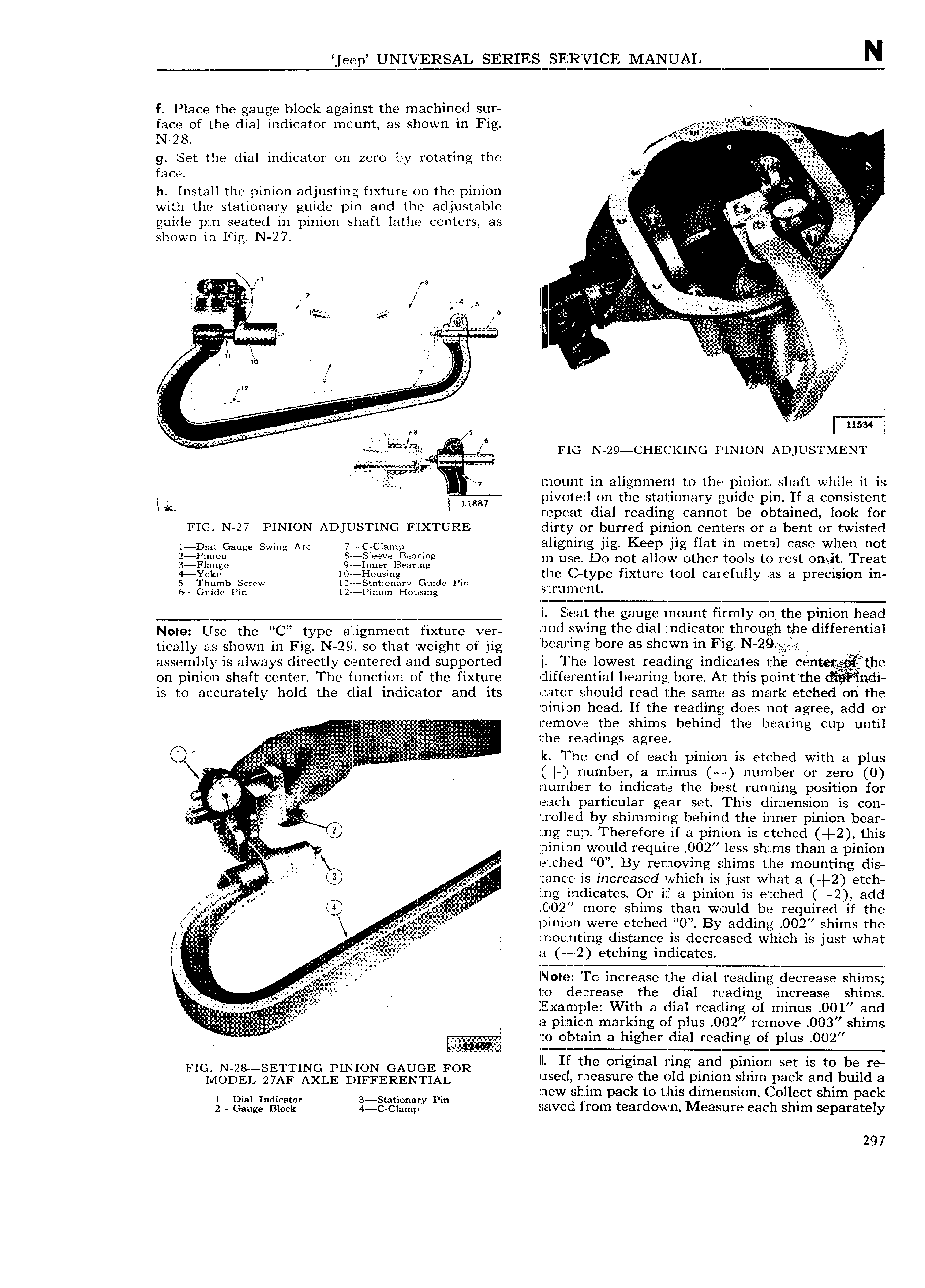
eep UNIVERSAL SERIES I SERVICE MANUAL N f Place the gauge block against the machined sur I QW face of the dial indicator mount as shown in Fig N 28 O I g Set the dial indicator on zero by rotating the I ieee i t ln Install the pinion adjusting fixture on the pinion Villn V r with the stationary guide pin and the adjustable ee V guide pin seated in pinion shaft lathe centers as 0 V V shown iii Fig N 2 7 i z I l I i T I E it i i y ai I I Q r A l II JT EI an we 2 1 W 5 6 I I t it u it n 1a i i i i i I l i i i I I is i i IL i v Vi i I izt i ii i I iusse I IB 8 In 5 6 I i i Hi I FIG N 29 CI ECKING PINION ADJUSTMENT s Mi i t F i E I sy mount in alignment to the pinion shaft while it is I W I pivoted on the stationary guide pin If a consistent Wt repeat dial reading cannot be obtained look for FIGI N 27 PINION ADJUSTJING FIXTURE dirty or burred pinion centers or a bent or twisted I DIaI Gauge Swmg Am 7 C CIamI l aligning jig Keep jig flat in metal case when not gjgigifgng gj fBE j g in use Do not allow other tools to rest onait Treat 3 jggke b S If I toiising G H P the C t ype fixture tool carefully as a precision in W 8 il Eae u 3 pi i2 1 t ieiia1 t sa Q t rr 2 ie t i Seat the gauge mount firmly on the pinion head Note Use the fC type alignment fixture ver i i dl Vi g thi dial indicator through hhe differential tieaiiy as shown in Fig N 29 i so that weight or ng f iij s b i as Shw ir Fig I assembly is always directly centered and supported i I he lowest reading indicates the cen fthe on pinion shaft center The f unc tion of the fixture 1 liffe1 ential bearing bore At this point the indi ls to accurately hold the dial indicator and its Gator should read the same as mark etched on the pinion head If the reading does not agree add or z i he shims behind the bearin cu until 3 i f I IN IT OV F g p v i the i di gS agree Q EIPE I lr The end of each pinion is etched with a plus yl V tf number a m inus number or zero 0 I I ll 1l1l lT b 1 to indicate the best running position for i EE iEl Z7l 1l particular gear set This dimension is con i ilrolled by shimming behind the inner pinion bear 0 ing c uj Therefore if a pinion is etched 2 this xi I i V itiinion would require 002 less shims than a pinion E E trtclhed 0 By removing shims the mounting dis 3 Ig il anc e is increased which is just what a 2 etch i ing indicates Or if a pinion is etched 2 add 4 ia U O2 more shims than would be required if the X jpinion were etched 0 By adding O 2 shims the V mounting distance is decreased which is just what izzl 2 etching indicates J J i N le To increase the dial readin r decr h I I g ease s ims E to decrease the dial reading increase shims IA H I llEZixa mple With a dial reading of minus 001 and g in pinion marking of plus 0O2 remove 003 shims to obtain a higher dial reading of plus 0O2 t t T M FIGI N 28 SETTING PINION GAUGE FOR II I Ilf the original ring and pinion set is to be re IWODEL 27AF AXLE DIFFERENTIAL usecl measure the old pinion shim pack and bu1ld a l Dial Indicator 3 Smi0mry Pin new shnm pack to this dimension ollect shim pack 2 Gaug Block t c Ci mp saved from teardown Measure each shim separately 297

 Next
Next