Ford Parts Wiki | GM Parts Wiki
Home | Search | Browse
Prev

 Next
Next
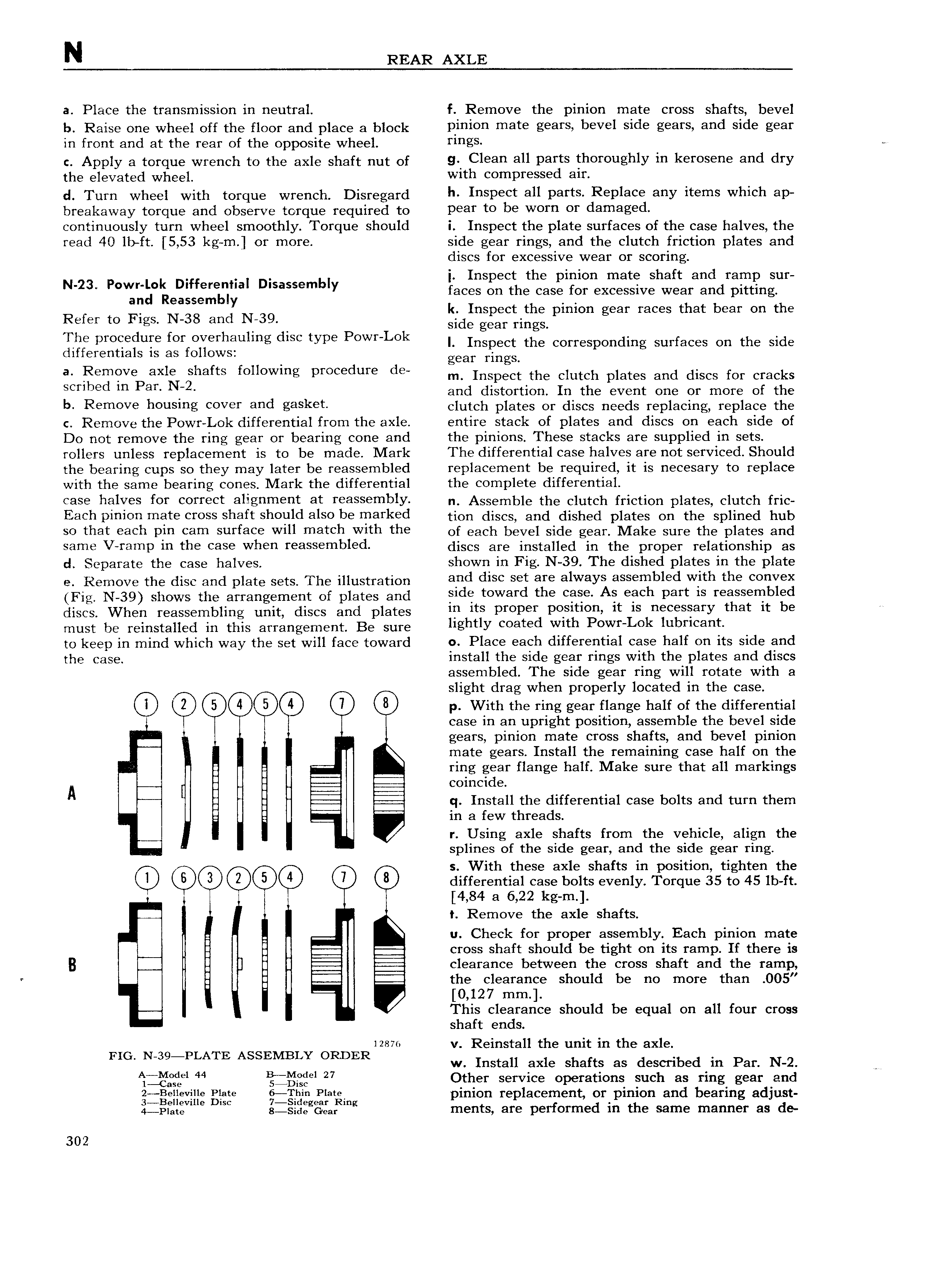
N REAR AXLE a Place the transmission in neutral f Remove the pinion mate cross shafts bevel b Raise one wheel off the floor and place a block Rlnlen mate gears bevel side gears and side gear in front and at the rear of the opposite wheel rlngs ce e Apply o torque wrench to the axle short nut of si leleaa all pags thereughly in keresepe and dry the elevated wheel Wlt eembresse all d Tum wheel with torque wreuoh Disresord h laspect all parts Replace aay items which ap breakaway torque and observe torque required to pear te be warn er damaged continuously turn wheel smoothly Torque should i Inspect the plate surfaces of the case halves the read 40 lb ft 5 53 kg rn or more side gear rings and the clutch friction plates and discs for excessive wear or scoring i Inspect the pinion mate shaft and ramp sur N 23 P V l if l al Dlsassembly faces on the case for excessive wear and pitting k Inspect the pinion gear races that bear on the Refer to Figs N 38 and l l 39 I Side gear rings The ameedure fer everhaulme dsc was Pewelels I rospeet the corresponding surfaces on the side differentials is as follows gear rings a R m V axlg shafts following procedure dB m Inspect the clutch plates and discs for cracks Scrlbed m Pen 2 and distortion In the event one or more of the b Rem0Ve nellslng cever and gasket clutch plates or discs needs replacing replace the c Remove the Powr Lok differential from the axle entire stack of plates and discs on each side of Do not remove the ring gear or bearing cone and the pinions These stacks are supplied in sets rollers unless replacement is to be made Mark The differential case halves are not serviced Should the bearing cups so they may later be reassembled replacement be required it is necesary to replace with the same bearing cones Mark the differential the complete differential case halves fer ccrrect allgnment at reassembly n Assemble the clutch friction plates clutch fric Each pinion mate cross shaft should also be marked tion discs and dished plates On the spiiyisd hub 0 rnali eatin Pln cam surface will marell Wlrn the of each bevel side gear Make sure the plates and Same V ramp in the Case Wllen reassembled discs are installed in the proper relationship as d Separate the case halves shown in Fig N 39 The dished plates in the plate e Remove the disc and plate sets The illustration and dlse set are always assembled W ltl l the eellvex Fig N 39 shows the arrangement of plates and jslde teward the ease As each Part ls reassembled discs When reassembling unit discs and plates lb lls PlePel Pdsltlbllw lt ls lleeessalY that lt be must be reinstalled in this arrangement Be sure llgllllY sealed Wltll PeWl LOk lllbrleallt to keep in mind which way the set will face toward 0 Place each differential case half on its side and the case install the side gear rings with the plates and discs assembled The side gear ring will rotate with a slight drag when properly located in the case C 4 0 p With the ring gear flange half of the differential case in an upright position assemble the bevel side gears pinion mate cross shafts and bevel pinion mate gears Install the remaining case half on the l ring gear flange half Make sure that all markings i coincide A i q Install the differential case bolts and turn them in a few threads I X r Using axle shafts from the vehicle align the splines of the side gear and the side gear ring s With these axle shafts in position tighten the Q QD 3 Q 6 differential case bolts evenly Torque 35 to 45 lb ft 4 84 a 6 22 kg rn t Remove the axle shafts u Check for proper assembly Each pinion mate 2 cross shaft should be tight on its ramp If there is B clearance between the cross shaft and the ramp r i the clearance should be no more than O05 0 127 mm This clearance should be equal on all four cross shaft ends L A izmo v Reinstall the unit in the axle FIG N 39 P ATE SSEMBLY ORDER w Install axle shafts as described in Par N 2 ijlggiel 44 l lg l 27 Other service operations such as ring gear and ge eviHe glare l2ii g Plas pinion replacement or pinion and bearing adjust 9 QV E ISC l E 98f lng 4 p1o e g s de Goa ments ate p I fOI H 1 d lf the Same lT1al lI 1 I as de 302

 Next
Next