Ford Parts Wiki | GM Parts Wiki
Home | Search | Browse
Prev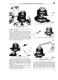
 Next
Next
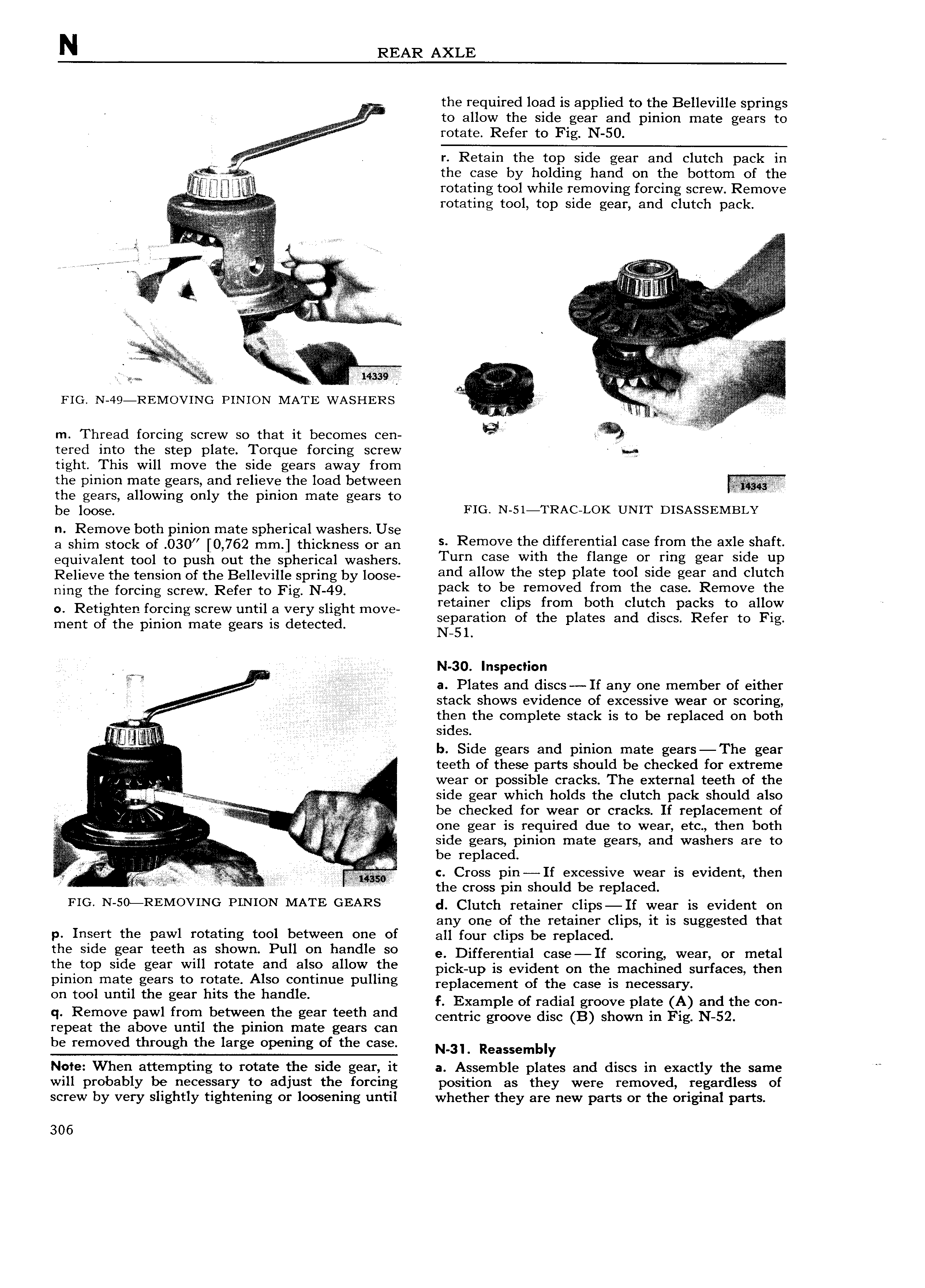
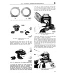
N REAR AXLE the required load is applied to the Belleville springs to allow the side gear and pinion mate gears to rotate Refer to Fig N 50 We Vl iviiiv r Retain the top side gear and clutch pack in V the case by holding hand on the bottom of the E i rotating tool while removin forcin screw Remove iw g g V V rotating tool top side gear and clutch pack e i tii i e airi tt QZ atlg e ri atat y I iitt yy tava I it r VV E l i T r l E E i i V g g Vgnkggt n lvlg r VV V lr I A V ite I G I F e I iii i iiii I I ee i I Y i izi1 V i Wi r 5 lv e i Y Ymw L FIG N 49 REMOVING PINION MATE wAsn1 Rs r i i V l t i m Thread forcing screw so that it becomes cen g A Z iii tered into the step plate Torque forcing screw tight This will move the side gears away from the pinion mate gears and relieve the load between the gears allowing only the pinion mate gears to ii iii i i bg OOS FIG N 5l TRAC LOK UNIT DISASSEMBLY n Remove both pinion mate spherical washers Use M s Remove the differential case from the axle shaft a shim stock of 030 0 762 mm thickness or an equivalent tool to push out the spherical washers Turn ease Wlm the flange oY Ymg gear Slde UP Relieve the tension of the Belleville sprang by loose eed eiiew the Step plete tee Side gear end clutch ning the forcing screw Refer to Fig N 49 Pad te be refgeved frem the ease Remove the 0 Retighten forcing screw until a very slight move retamiii C lp trfomi lioth Cgugh palgksr tot algiw A ment of the pinion mate gears is detected iegaira um O G P 3 ee ee mcs G ee O lg em N 30 Inspection i i A il 2 a Plates and discs If any one member of either ff stack shows evidence of excessive wear or scoring as A then the complete stack is to be replaced on both r sides l I b Side gears and pinion mate gears The gear ii i teeth of these parts should be checked for extreme r sk 1 wear or possible cracks The external teeth of the A 5l A w e side gear which holds the clutch pack should also V Viax in v Y be checked for wear or cracks If replacement of J i i i one gear is required due to wear etc then both l M sc side gears pinion mate gears and washers are to i i q A be replaced if fi s c c Cross pin If excessive wear is evident then F es I e the cross pm should be replaced FIG N 5o REMoVING PINION MATE GEARS d Clutch retainer clips If wear is evident on any one of the retainer clips it is suggested that p Insert the pawl rotating tool between one of all four clips be replaced the Side geef teeth ee ehewe Pull ee heedle Se e Differential case 1r scoring wear or mai me top sloe eeer Wlll retete and also allow the pick up is evident on the machined surfaces then pinion mate gears to rotate Also continue pulling replacement cf the case is necessary On mol umd the gear hits the handle f Example of radial groove plate A and the con q Remove pawl from between the gear teeth and centric groove disc B shown in Fig N 52 repeat the above until the pinion mate gears can be removed through the large opening of the case N 3L Reassembly Note When attempting to rotate the side gear it a Assemble plates and discs in exactly the same will probably be necessary to adjust the forcing position as they were removed regardless of screw by very slightly tightening or loosening until whether they are new parts or the original parts 306