Ford Parts Wiki | GM Parts Wiki
Home | Search | Browse
Prev
 Next
Next
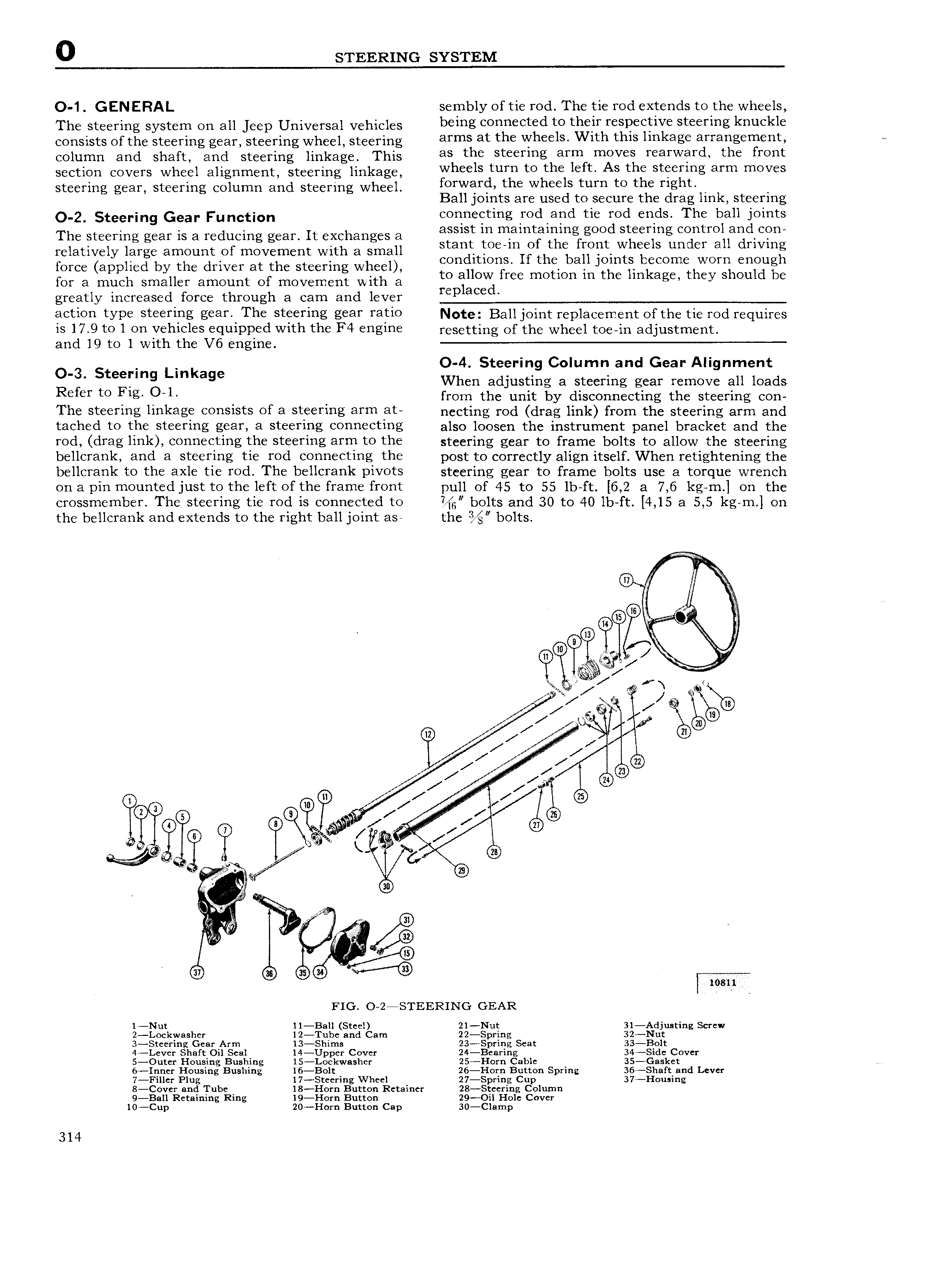
0 STEERING SYSTEM O 1 GENERAL sembly of tie rod The tie rod extends to the wheels The Steering System On eil Jeep Universai Vehicles being connected t0 their respective steering knuckle consists of the steering gear steering wheel steering arms nt the Wheels Wlth thls hhkege arrangement e column and shaft and steering linkage This as the steetlhg htm thOVes reerWerd the heht section covers wheel alignment steering linkage Wheels turn to the left AS the steerlng erm moves steering gear steering column and steering wheel g riie rd tthe Wheegstturh to tele Y lghti k t V a Join s are use o secure e rag in s eerlng 0 2 Steering Gear Function connecting rod and tie rod ends The ball joints The steering gear is a reducing gear lt exchanges a ages in mamtgltggngf gmtd Sferfng 1 tY giagd relatively large amount of movement with a small S 31 i t O imI th 1 it S un GY 3 I Wing force applied by the driver at the steering wheel COHIE IOY C 3 wm iicomc WON cnoug for a much smaller amount of movement with a mi OW me motmn m the m 3g they ShOuld be greatly increased force through a cam and lever mp ac d eletlell type steellflg gear The Steelllig gear l 3tl0 Note Balljoint replacement of the tie rod requires is 17 9 to 1 on vehicles equipped with the F4 engine resetting Of the Wheel tOs in adjustm nt and 19 to 1 with the V6 engine O 4 Steerin Column and Gear All nment O 3 Steering Linkage 9 g When adjusting a steering gear remove all loads Refer to Flg O 1 from the unit by disconnecting the steering con The steering linkage consists of n steering erm et necting rod drag link from the steering arm and tached to the Steeflng ge lfi 3 Steeflng 0 l 1e l g also loosen the instrument panel bracket and the rod drag link connecting the steering arrn to the steering gear to frame bolts to allow the steering bellcrank and 3 Steering tie fod Connecting the post to correctly align itself When retightening the bellcrank to the axle tie rod The bellcrank pivots steering gear to frame bolts use a torque wrench on a pin mountedjust to the left of the frame front pull of 45 to 55 lb ft 6 2 a 7 6 kg m on the crossmember The steering tie rod is connected to Hg bolts and 30 to 40 lb ft 4 15 a 5 5 kg m on the bellcrank and extends to the right ball joint asa the bolts Te l WM ii 00 i rm Qi A e 7 ii Q ww Q V v e AP e g Q V Q 1 Q V V G 0 s e i ce l srl G 4 e o e o W man FIG O 2 STEERING GEAR 1 Nut ll Ball Steel 21 Nut 31 Adjusting Screw 2 Lockwasher 12 Tube and Cam 22 Spring 324 Nut 3 Steering Gear Arm 13 Shims 23 Spring Seat 33 B0lt 4 Lever Shaft Oil Seal 14 Upper Cover 24 Bearing 34 Sidc Cover 5 Outer Housing Bushing 15 Lockwasher 25 Horn Cable 35 Gasket 6 Inncr Housing Bushing 16 Bo1t 26 Horn Button Spring 36 Shaft and Lever 7 Fillcr Plug 17 Steering Wheel 27 Spring Cup 37 Housing 8 Cover and Tube 18 Horn Button Retainer 28 Steering Column 9 Ball Retaining Ring 19 Horn Button 29 Oil Hole Cover 10 Cup 20 Horn Button Cap 30 Cl mp 314