Ford Parts Wiki | GM Parts Wiki
Home | Search | Browse
Prev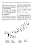
 Next
Next
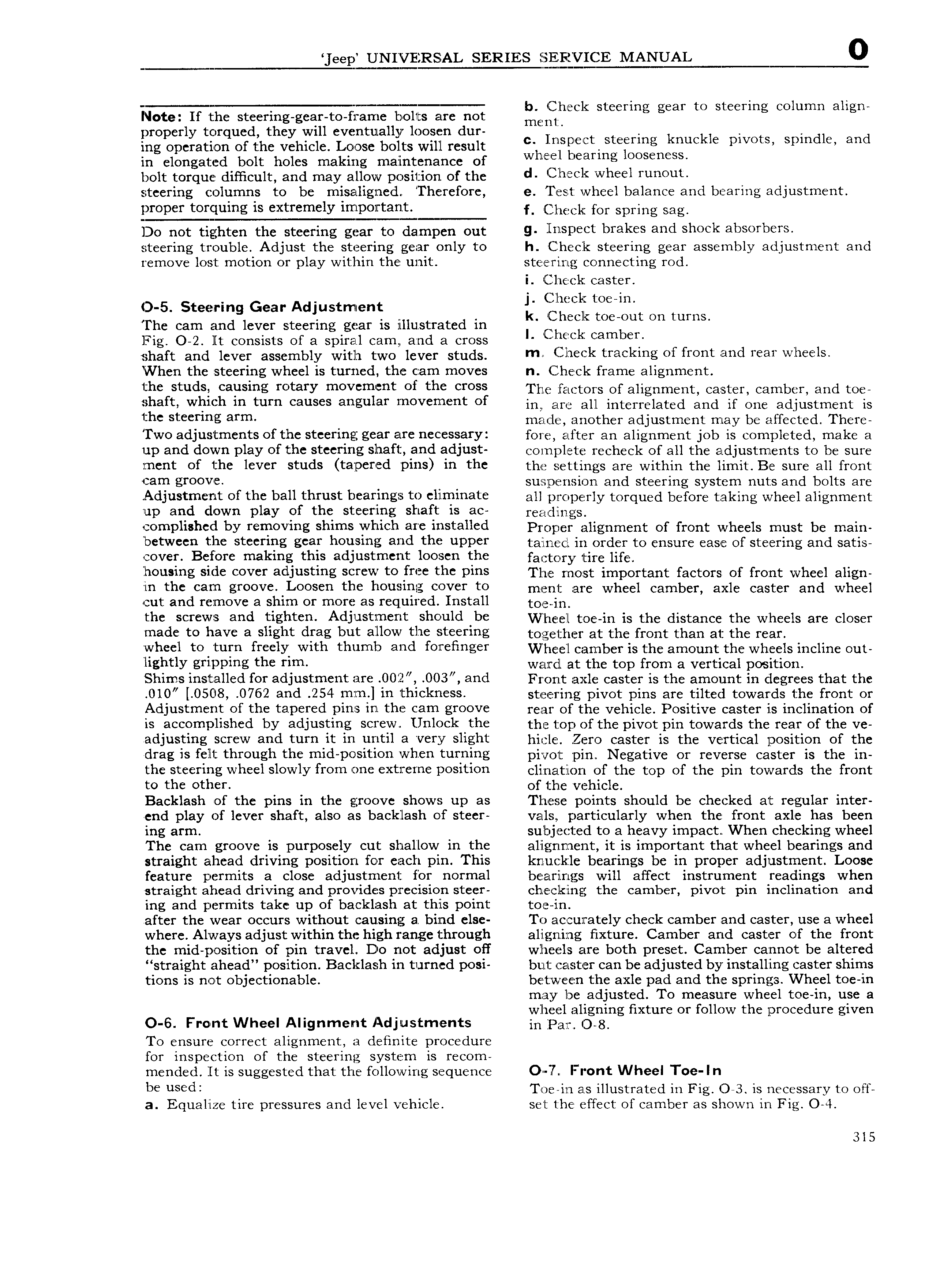
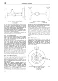
eep UNIVERSAL SERIES IEEEEVEFVICIE MANUAL 0 1 7 r b Che 1 t t t l l Note If the steering gear to frame bolts are not mm 1 C S ecrmg gem O S Ccrmg CO umn a lgn properly torqued they will eventually loosen dur t t k kl t dl d ing operation of the vehicle Loose bolts will result h ECC S rmg mc C PWO S Spm 6 ee in elongated bolt holes making maintenance of W lf eafmg O S n SS bolt torque diiiicult and may allow position of the d h 5 l Wh l TUUOUC steering columns to be misalignedi Therefore e Test wheel balance and bearing adjustment proper torfluing is extremely f jil le l for spring sag Do not tighten the steering gear to dampen out 9 lrisbeet brekes end sbeek absorbers steering trouble Adjust the steering gear only to h Check steering gear assembly adjustment and remove lost motion or play within the unit stee ririg connecting rod i C l ieck caster O 5 Steering Gear Adjustmuent 5Ef j Li 1n t t The cam and lever steering gear is illustrated in I ff IO Ou On umS Fig O 2 lt consists of a spiral cam and a cross i k Cambeh shaft and lever assembly with two lever studs m be l trsekrng ef frontend reer wheels When the steering wheel is turned the cram moves n Check frame alignment the studs Calming mtary mOV m t ef the Cross The factors of alignment caster camber and toe i 11aft whi h in turn Cal1S S 3I 1gl1l 3I lTTlOV U3 t of in are all interrelated and if One 3Cljl1St1 Yl I1 E is C S cI m g a m macle another adjustment may be affected There I wo adjustments of the steering gear are neccessary fore after an alignment job is completed make a up and down play of the steering shaft and adjust complete recheck of all the adjustments to be sure ment of the lever studs tapered pins in the the settings are within the limit Be sure all front cam groove suwperision and steering system nuts and bolts are Adjust 1ne it of th ballfthigist bearings ts llll IllH3t all properly torqued before taking wheel alignment up an Own pay O I C St CI ilI 1g S la t 1S 3C re l llngs cornplished by removing shims which are installed Proper alignment of front wheels must be main betweer tjae steer1 ng gelar hilusing and lthfr llppgf tained in order to ensure ease of steering and satis cover e ore ma lng t IS 2 justmcilf OOSCH t fa t ory tire life houing side cover adljusting slelrevlg to free the pins The rnosst important factors of front wheel align in t e cam groove oosen t e rousing cover to me n l are wheel camber axle caster and wheel cut and rernove a shim or more as req uired Install toe in thed screvirs and Figlhtegi l t j l lSiZlH lC1 lt lshould be W heeel toe in is the distance the wheels are closer ma e to iave a s ig t rag ut al ow tie Steering together at the front than at the rear jizvhleil to turn frleely with thumb and forefinger Wheel camber is the amount the wheels incline out ig t y gripping t e rim warcl at the top from a vertical position Shims installed for adjustment are 00i2 0O3 and Front axle caster is the amount in degrees that the 0l0 0508 0762 and 254 mm in thickness steering pivot pins are tilted towards the front or Adjustment of the ta pered pins in the cam groove reai of the vehicle Positive caster i s inclination of is accomplished by adjusting screw Unlock the the top of the pivot pin towards the rear of the ve adjusting screw and turn it in until a very slight hitile Zero caster is the vertical position of the drag is felt through the mid position when turning pivot pin Negative or reverse caster is the in the steeriiig wheel slowly from one extreme position clisnatlon of the top of the pin towards the front to the ot ier of the vehicle Backlash of the pins in the groove shows up as These points should be checked at regular inter end play of lever shaft also as backlash of steer vals particularly when the front axle has been ing arm subjeelzed to a heavy impact When checking wheel The cam groove is purposely cut shallow in the alignment it is important that wheel bearings and straight ahead driving position for each pin This knu i k le bearings be in proper adjustment Loose feature permits a close adjustment for normal bearings will affect instrument readings when straight ahead driving and provides precision steer chl eelkEing the camber pivot pin inclination and ing and permits take up of backlash at this point toe in after the wear occurs without causing a bind else To accurately check camber and caster use a wheel where Always adjust within the high range through aligning fixture Camber and caster of the front the mid position of pin travel Do not adjust off wheels are both preset Camber cannot be altered straight ahead position Backlash in turned posi but easter can be adjusted by installing caster shims tions is not objectionable betweecn t he axle pad and the springs Wheel toe in may be adjusted To measure wheel toe in use a O 6 F Wh A Ad wheel aligning fixture or follow the procedure given ront eel lignment justments injrzal Org To ensure correct alignment a definite procedure for inspection of the steering system is recom mended lt is suggested that the following sequence O Y Front Wheel Toe I n be u d Toe in as illustrated in Fig O 3 is necessary to off a Equalize tire pressures and level vehicle set the effect of camber as shown in Fig O 4 315