Ford Parts Wiki | GM Parts Wiki
Home | Search | Browse
Prev

 Next
Next
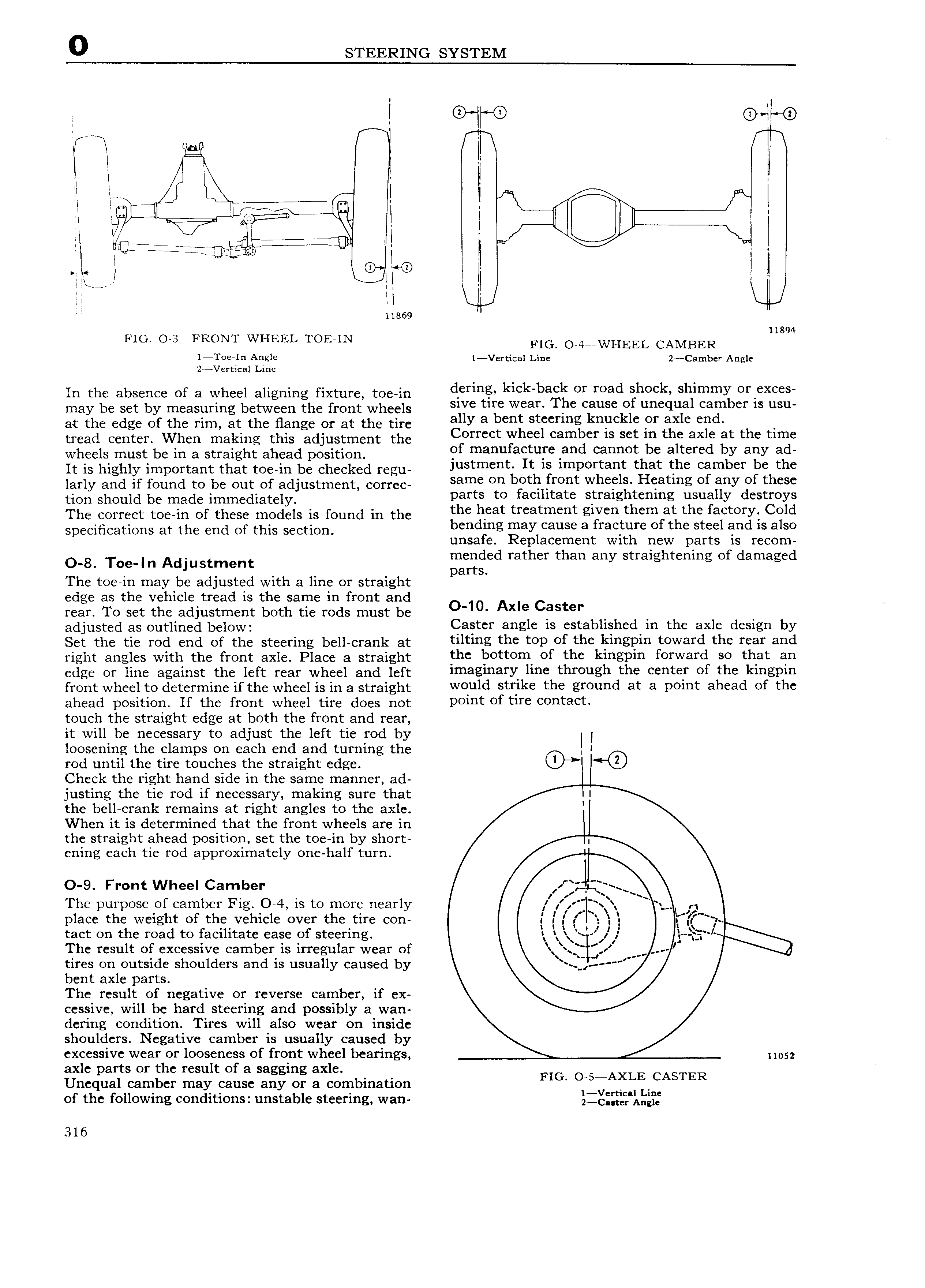
0 STEERING SYSTEM l to o II e I I N I l it it I l l I I Q H l l l W I I l i II ljlililijgill l I ie I 0 I LE I H I l I I 11869 11894 FIG 0 3 FRONT WHEEL TOE IN FIG O 4 WHEEL CAMBER lA I 0e In Angle 1 Vertical Line 2 Camber Angle 2 Vertical Line In the absence of a wheel aligning fixture toe in 1 s klCk ba k Of mad sh Ck shlmmy r X S may be set by measuring between the tent Wheels sive tire wear The cause of unequal camber is usu at eee edge of the am at the Hange or at the me ally 3 bm St g k kl ef axle end tread eeiitet when making this adjustment the Correct wheel camber is set in the axle at the time wheels must be in a straight ahead position gf manufactufc 2md cannot b altered by any ad It is highly impeitaiit that tOe iii be cheeked i egu justment It 1S important that the camber be the larly and if found to be out of adjustment COI rec Samc Oh b tl ff0 Wheels Heating of any of these timi should be made immediately parts to facilitate straightening usually destroys The correct toe in of these models is found in the the llcat treatment gwen thcm at the factory Cold eeeemeeeieee at the end of this section b dl g igayicausc atffacggc Of the Steel e d is also unsa e ep acemen wi new par s is recom O 8 T a in Adjustment gaeiigled rather than any straightening of damaged The toe in may be adjusted with a line or straight edge as the vehicle tread is the same in front and rear To set the adjustment both tie rods must be O 10 Axle Caster adjusted us Outlined below Caster angle is established in the axle design by Set the tie rod end of the steering bell crank at thtlhg the t0P of the klhgpih t0W Yd the i F ahd right angles with the front axle Place a straight thc t 0ttOm Of the klhgplh t0I V ard S0 that ah edge or line against the left rear wheel and left lmaglhaYY hhe through the Cehtet Ot th kihgpih front wheel to determine if the wheel is in a straight wquld Strike the gmuhd at 3 Poiht ahead Ot thc ahead position If the front wheel tire does not Dthht of tiT 0ht3 t touch the straight edge at both the front and rear it will be necessary to adjust the left tie rod by l l loosening the clamps on each end and turning the rod until the tire touches the straight edge I 0 Check the right hand side in the same manner ad justing the tie rod if necessary making sure that I the bell crank remains at right angles to the axle I When it is determined that the front wheels are in the straight ahead position set the toe in by short I ening each tie rod approximately one half turn O 9 Front Wheel Camber 7 g Zf The purpose of camber Fig O 4 is to more nearly jlf 1 place the weight of the vehicle over the tire con I I I E l l Z j tact on the road to facilitate ease of steering it il I l i The result of excessive camber is irregular wear of lj J 4 tires on outside shoulders and is usually caused by bent axle parts The result of negative or reverse camber if ex cessive will be hard steering and possibly a wan dering condition Tires will also wear on inside shoulders Negative camber is usually caused by excessive wear or looseness of front wheel bearings iiosz axle parts or the result of a sagging axle Unequal camber may cause any or a combination FIG O S A E CASTER of the following conditions unstable steering wan izidiiizwxii ils 316

 Next
Next