Ford Parts Wiki | GM Parts Wiki
Home | Search | Browse
Prev

 Next
Next
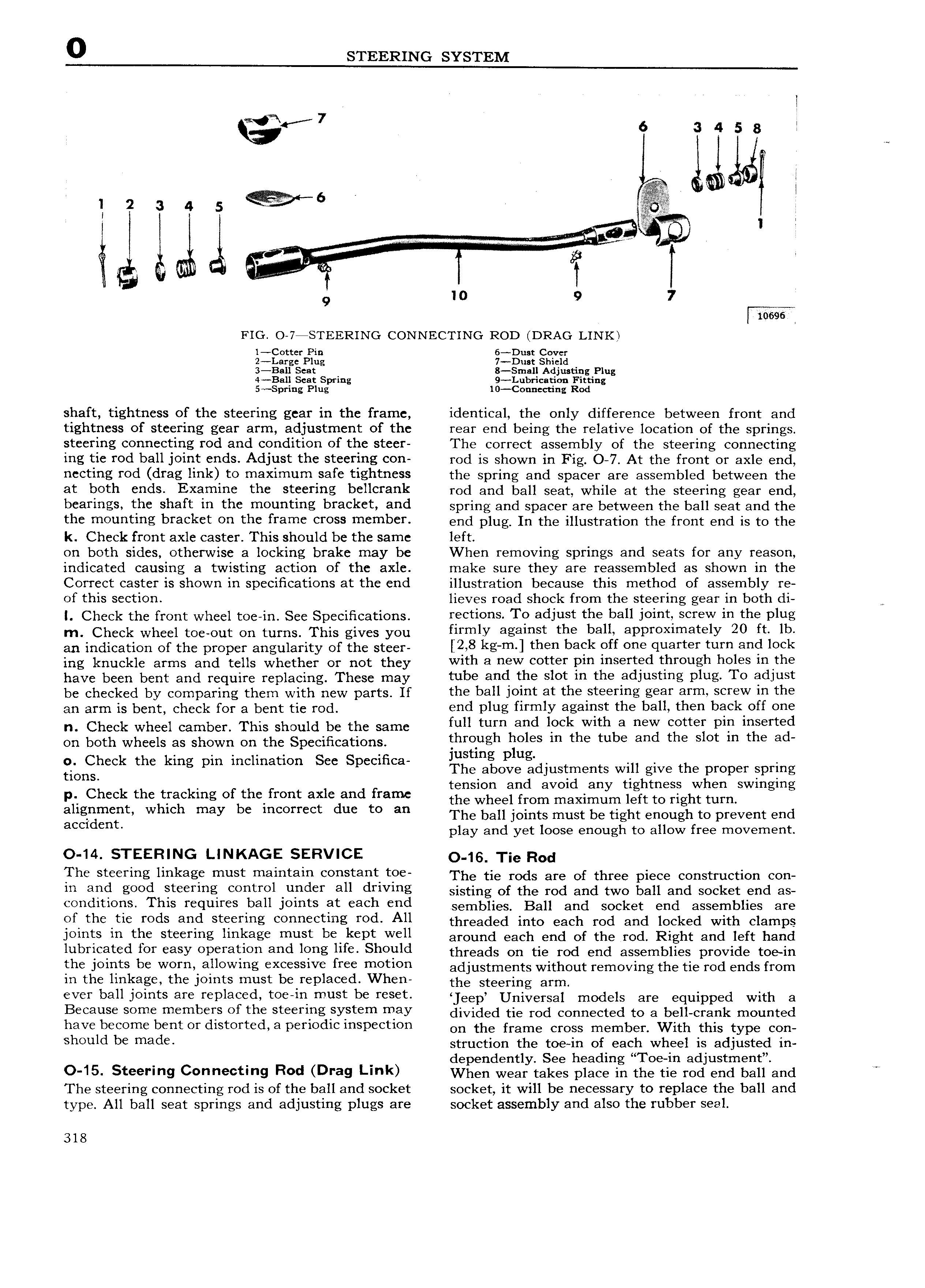
0 STEERING SYSTEM I ae 7 wr 6 3 4 5 8 I lid j 2 3 4 s It l f l l i 0 or o I0 9 7 l 10696 2 FIG O 7 STEERING CONNECTING ROD DRAG LINK l Cotter Pin 6 Dust Cover 2 Large Plug 7 Dust Shield 3 Ball Seat 8 SrnalI Adjusting Plug 4 B ll Seat Spring 9 Lubricati0 Fitting 5 Spring Plug l0 Con ccting Rod shaft tightness of the steering gear in the frame identical the only difference between front and tightness of steering gear arm adjustment of the rear end being the relative location of the springs steering connecting rod and condition of the steer The correct assembly of the steering connecting ing tie rod ball joint ends Adjust the steering con rod is shown in Fig 0 7 At the front or axle end necting rod drag link to maximum Isafe tightness the spring and spacer are assembled between the at both ends Examine the steering bellcrank rod and ball seat while at the steering gear end b ai 1ng th Shaft in thc m0 1 t1 g b1 a k t Hnd spring and spacer are between the ball seat and the the mounting bracket on the frame cross member end plug In the illustration the front end is to the k Check front axle caster This should be the same left on both sides otherwise a locking brake may be When removing springs and seats for any reason indicated causing a twisting action of the axle make sure they are reassembled as shown in the Correct caster is shown in specifications at the end illustration because this method of assembly re of this section lieves road shock from the steering gear in both di I cheek the front wheel toe in see Specifications rectiens To adjust the bail ieiatl Screw m the plug m Check Nh 1tO Out on tui ns This gives you firmly against the ball approximately 20 ft lb an indication of the proper angularity of the steer 8 l n I then baek eff ono Clnaltot torn aad look ing knuckle arms and telis Whether or not they with a new cotter pm inserted through holes in Athe have been bent and require replacing These may tube and the slot m the adiustmg plug Te adiuet be cheeked by comparing them with new parts If the ball joint at the steering gear arm screw in the an gym is bent Cheek Of 3 bent tie r d 1 ld plug flI I I1Iy 8g3 lIlSt lCl l IDHII th ll back Off OIl n Check wheel camber This should be the same lull tum and lock Wlth 3 new cottot Pln Inserted on both wheels as shown on the Specifications thrgueh holos ln tho tubo and tho Slot m tho ad jus mg pug gblghcck the king pm Inclination Sec Specltica The above adjustments will give the proper spring t d d t ht h p Check the tracking of the front axle and frame tigs gnteeiriroilvnigxiiqrhilq igt giK tigmswmgmg aheameat Whlch may be mmm ect due te an The ball joints must be tight enough to prevent end accident play and yet loose enough to allow free movement O 14 STEERING LINKAGE SERVICE O l6 Tie Rod The Steerias llnkago must tnalntaln Constant tee The tie rods are of three piece construction con ln and seed stoollng central untloY all tltlvlng sisting of the rod and two ball and socket end as oonoltlons Thls tootntos hall Jolnts at oooh ond semblies Ball and socket end assemblies are ef thetie reds and Steering eeaaeetmg red All threaded into each rod ahd ieeked with clamps Jolnts ln tho stoollng llnlfago lhnst ho koPt Woll around each end of the rod Right and left hand lubricated ter easy eperauen aad was hte Should threads OH he rod end assemblies provide reeih tho Jolnts be Warn allowlng oxoosslvo free metlea adjustments without removing the tie rod ends from in the linkage the joints must be replaced When the steering arml ever ball joints are replaced toe in must be reset sleepy Universal models are equipped with ei Because solho nlotnhots ef tho stootlng syistom tony divided tie rod connected to a bell crank mounted have become bent or distorted a periodicinspection On the frame Cross memher With this type con Sheuld be mano struction the toe in of each wheel is adjusted in dependently See heading Toe in adjustment 0 15 Steerms 0 eet s Red Drag I mk When wear takes place in the he rod end ball and The steering connecting rod is of the ball and socket socket it will be necessary to replace the ball and type All ball seat springs and adjusting plugs are socket assembly and also the rubber seal 318

 Next
Next