Ford Parts Wiki | GM Parts Wiki
Home | Search | Browse
Prev

 Next
Next
991381
920556
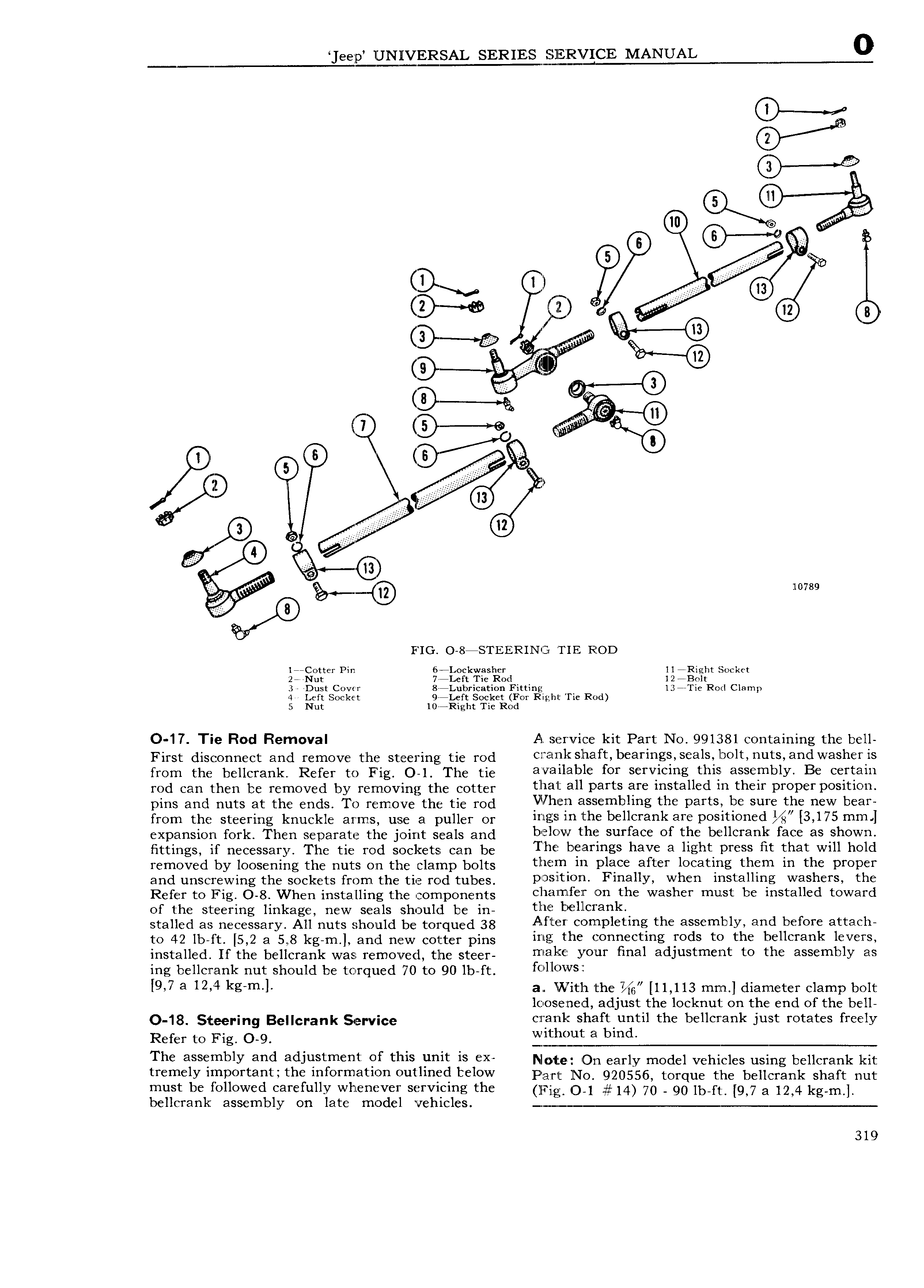
eeqp UNHESAL SERIES MANUAL 0 Q E e Gl is m p Kw Q rp A AA 2 1 8 v e resid s s 9 lg 3 G me rr 0 ll 2O www 0 YD E EEE A E AE l sstt r r AEA 6 l A4 G 7 gh W 9 I 9 10789 FIG 0 8msT1 ER1N TIE Roo 1 Cottcr Pin 6 Lockwasher 11 Right Socket 2 rNut 7 Left Tie Rod 12 Bolt 3 Dust Cover 8 Lubrication Fitting 13 Tie Rorl Clamp 4 Left Socket 9t Left Socket For Right Tie Rod 5 Nut 10t Right Tie Rod O 17 Tie Rod Removal A service kit Part N0 991381 containing the bell First disconnect and remove the steering tie md ClT l llYlk ll 18 ft b 8l ll lg S 3lS l3Olt 1 1 lts a1 1ClWaSher iis from the bellcrank Refer to Fig O 1 The tie 3 3lllab1 fst TYl mg this 8S f blY B6 T 3l rod can then be removed by removing tne potter tllial all parts are installed in their proper position pins and nuts at the ends To remove the tie rod lilllien assembling the partst be sure the new bear from the steering knuckle arms use a puller or U ll3 mlhe bellcr mk am PO lUO d 3 175 mm l expansion fork Then separate the joint seais and below the surface of the bellcrank face as shown fittings if necessary The tie rod sockets can be rum b 3I mgS haV 3 hgh PYCSS it Yhat Will hcld removed by loosening the nuts on the clamp bolts tl l lQ m Pl ce 3ft 1 l0 3 g th m IU th PYOPCF and unscrrewing the sockets from the tie rod tubes P lt O Fmaulh Wh installing Wa h YS th Refer to Fig O 8 When installing the components cliamier on the washer must be installed toward of the steering linkage new seals should be in tlrnt bellcrankn stalled as necessary All nuts should be terqued 38 After completing the assembly and before attach to 4Q 1 o i t 5 2 a 51 8 kg m and new eotter pins ing the connecting rods to the bellcrank levers installed If the bellcrank was removed the steer l2 lli y0 ll1 lillal adjustment to the assembly as ing bellcrank nut should be torqued 70 to 90 lb ft follows 2 9 7 3 12 4 kg m l a iN ith the 11 113 mm diameter clamp bolt lc os e ned adjust the locknut on the end of the bell O 18 Steering Bellcrank Service c r anl shaft until the bellcrank just rotates freely Refer to Fig O o witliout a bind The ssssrhhly ahd adjustmsht sf this uhh is sx waste On eany medei vemeies using beiierank kit tremely important the information outlined below Fngi put NO 920556 torque the bellcrank shaft nut must be followed carefully whenever servieing the iicrinn O 1 14 70 gg 1b ft 9 7 a 12 4 kg m bellcrank assembly on late model vehicles m m mm 319

 Next
Next