Ford Parts Wiki | GM Parts Wiki
Home | Search | Browse
Prev

 Next
Next
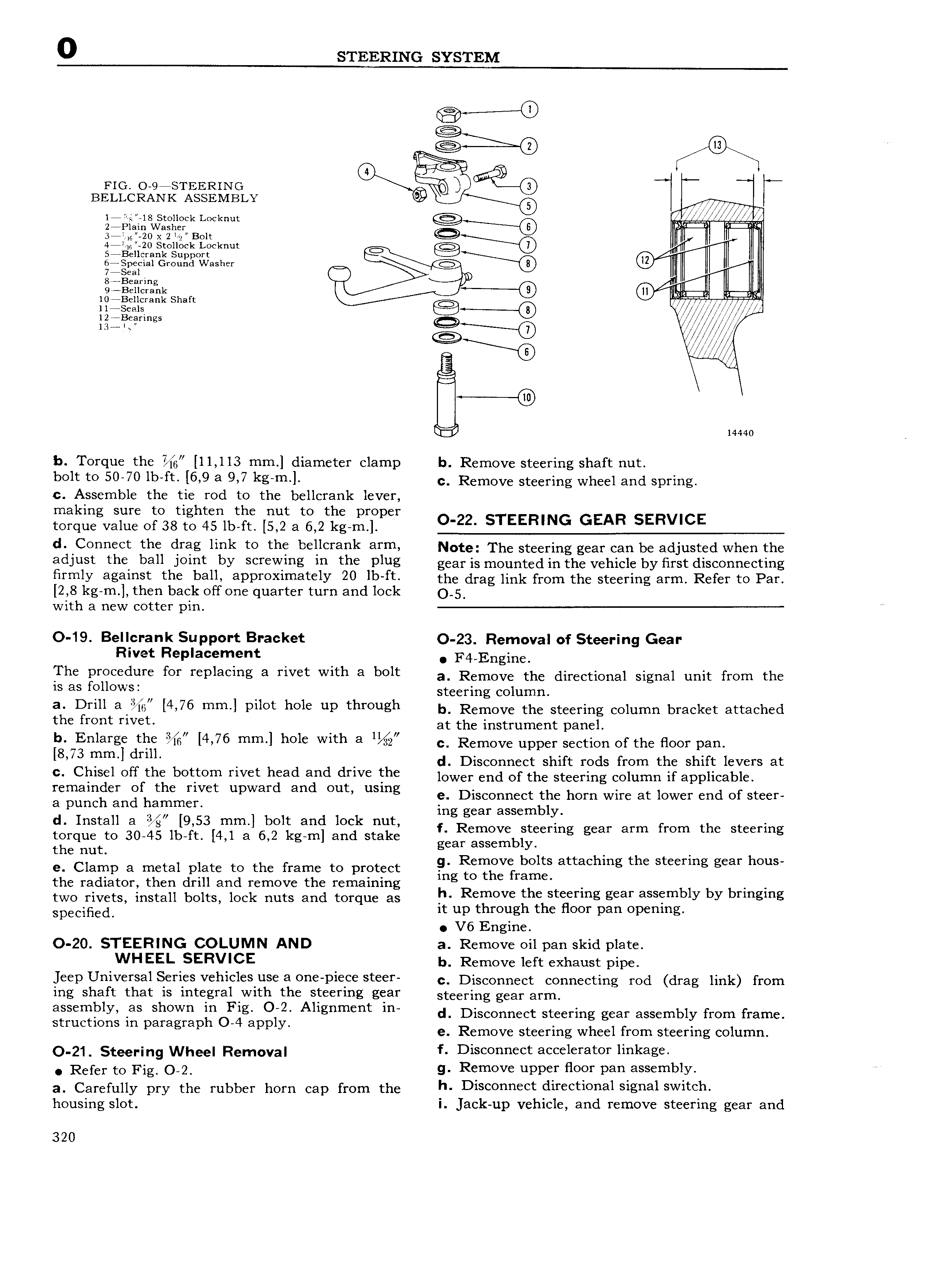
0 STEERING SYSTEM a 0 Flo O 9 STEERING BELLCRANK ASSEMBLY G 0 A j18v to lAlock Locknut s 6e eio Xe lie Bolt i 4 7 6 20 Stollock Locknut 5 Bel1crank Support Q 6 gpeplal Ground Washer 5 m C8 I ozazazlzar up llll ll ii 10 Bellcrank Shaft ll1s eg rrr r yy l l ee rio WMM W 4 14440 b Torque the 11 113 mm diameter clamp b Remove steering shaft nut bolt to 50 70 lb ft 6 9 a 9 7 kg m e Remove steering wheel and spring c Assemble the tie rod to the bellcrank lever making sure to tighten the nut to the proper torque value of 38 to 45 lb ft 5 2 a 6 2 kg m O 22 STEERING GEAR SERVICE d Connect the drag link to the bellcrank arm Note The steering gear can be adjusted when the adjust the ball Joint by screwing in the plug gear is mounted in the vehicle by iirst disconnecting firmly against the ball approximately 20 lb ft the drag link from the steering arm Refer to Par 2 8 kg m then back off one quarter turn and lock 5 with a new cotter pin O 19 Bellcrank Support Bracket O 23 Removal of Steering Gear Rivet Replacement F4 Engin The oroeedure ror remaemg a river with a bolt a Remove the directional signal unit from the rs as rouovvei U steering column a Drill a i i4 7o mm l poor hole up rhrough b Remove the steering column bracket attached the rroor rrvee l H at the instrument panel b Enlarge me i 4 7o mm hole vvrrh a 1 c Remove upper section of the floor pan 73 rem dem d Disconnect shift rods from the shift levers at Chisel orrfrhel boerom rrver head gid drrve the lower end of the steering column if applicable remainder e t e I wee upward en eee uemg c Disconnect the horn wire at lower end of steer a punch and hammer ing gear assembly d Install a 9 53 mm bolt and lock nut tgrque to 30 45 lb ft 4 1 a 6 2 kg m and stake g a irgixbfgeerlng gear erm rem the eteermg t e nut e Clamp a metal plate to the frame to protect liersgverbfggs atraehmg the steermg gear h S the radiator then drill and remove the remaining ng O e el two rivets install bolts lock nuts and torque as Remove the sreermg gear assembly by ormgmg Sp CiH d it up through the floor pan opening V6 Engine O 20 STEERING COLUMN AND a Remove oil pan skid plate WHEEL SERVICE b Remove left exhaust pipe jeep Universal Series vehicles use a one piece steer c Disconnect ccnnccting md drag ink frorn ing shaft that is integral with the steering gear Stccrgng gcay ayn ejserglgy ias l W 1 Orrgg Ol 2 Ahgnment m d Disconnect steering gear assembly from frame S me 1 n n P gr p pp y e Remove steering wheel from steering column g1 Stccr ing Whcc Rem ya f Disconnect accelerator linkage Refer to Fig O 2 g Remove upper floor pan assembly V a Carefully pry thc rubbcr horn can I cna thc h Disconnect directional S1g1 131SW1tCh housing slot l Jack up vehicle and remove steering gear and 320

 Next
Next