Ford Parts Wiki | GM Parts Wiki
Home | Search | Browse
Prev
 Next
Next
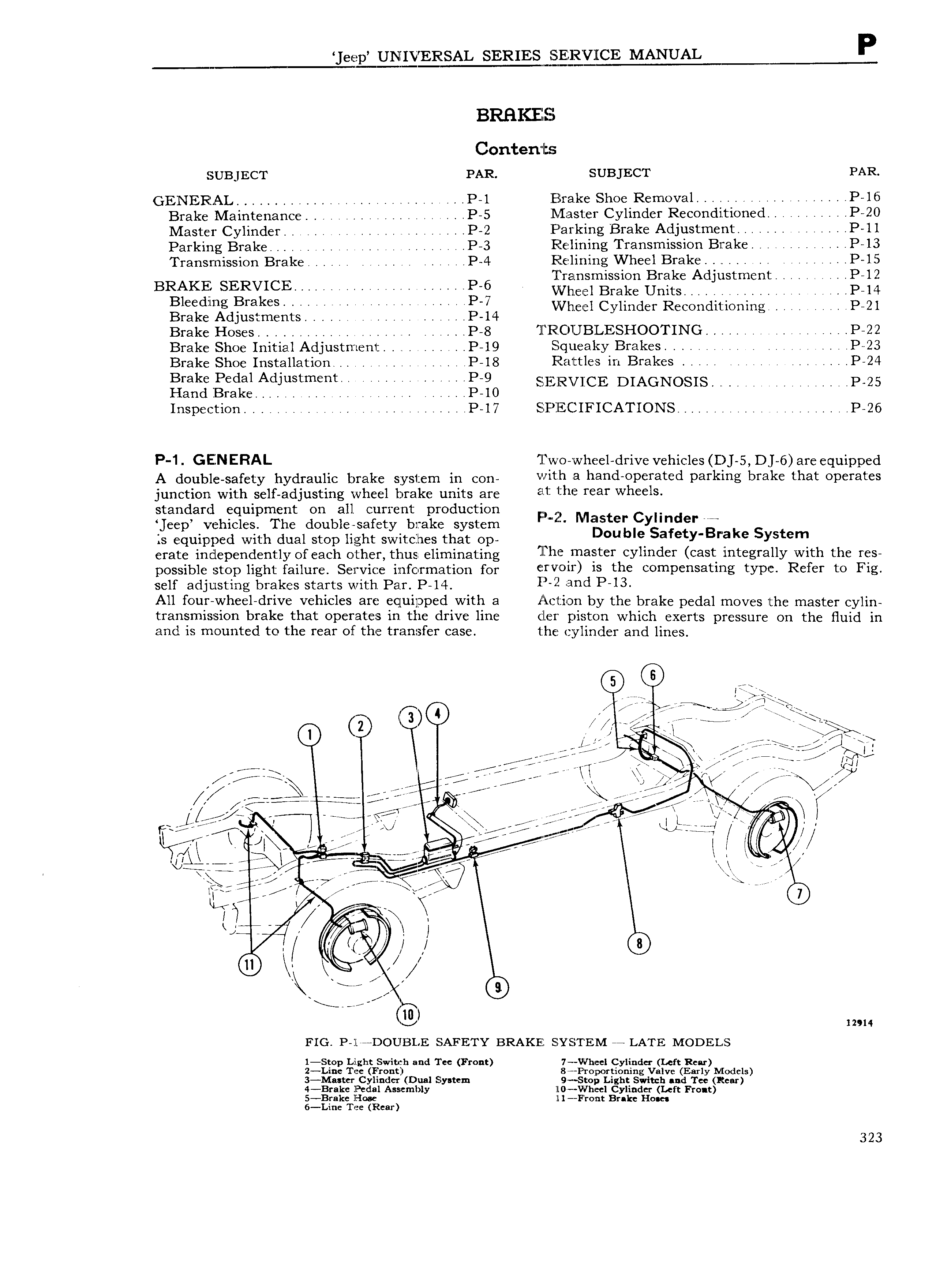
eep UNIVERSAL SERIESI i l CE MANUAL P BRHKELEES Contents SUBJECT PAR SUBJECT PAR GENERAL P 1 jElra ke Shoe Removal P 16 Brake Maintenance P 5 jMaste1 Cylinder Recondi tioned 4 P 20 Master Cylinder P 2 Parking Brake Adjustment A 4 P l1 Parking Brake V 4 P 3 Fiielining Transmission Brake P 13 Transmission Brake V P 4 Eilelining Wheel Brake A e r P l5 liransrnission Brake Adjustment rr P 12 BRAKE SERVICE v R6 v v e1 Brake Units r rrJ rr s P 14 Bleeding Brakes P 7 VVheel Cylinder Reconditioning P 21 Brake Adjustments l 4 P 14 Brake Hoses A 4 P 8 ll Rf OUBLESHOOTING r P 22 Brake Shoe Initial Adjustment 4 i P 19 Squeaky Brakes rr i V A P 23 Brake Shoe Installation V V P 18 Rattles in Brakes r r P 24 Bf k P d lAd5 1Stm t E 4i P 9 SE E RV CCE DIAGNOSIS r rr r r P 25 Hand Brake 4 P 10 Inspection V i P 17 EE PlE CIFICATIONS r P 26 P 1 GENERAL T X wo wheel drive vehicles D 5 D 6 are equipped A double safety hydraulic brake system in con V lt h 3 h B d 0P Y3t d Pafkmg bY3k that 0P Yat junction with self adjusting wheel brake units are at h ma Wh l standard equipment on all current production 3 eep vehicles The double safety brake system p r M t LFy nd r ig k S is equipped with dual stop light switches that op H u e afet R e Y t l erate independently of each other thus eliminating llhe master cylinder cast integrally with the res possible stop light failure Service information for f Y i OU is thc 0mP 3tmg YYDC R f Y to F1g self adjusting brakes starts with Par P 14 P 3f1d P I3 All four wheel drive vehicles are equipped with a x lcl i on by the brake pedal moves the master cylin transmission brake that operates in the drive line f er piston which exerts pressure on the Huid in and is mounted to the rear of the transfer case the cylinder and lines o A YQ 3 i5 sa I Mi ci or J C N ifE Q j ED jjjl V m 7 7 2 j K er i j ii r w A w I 1 X Z I 4 E E r E W i4E ii j A iii i RE T I iiii iY e A Fiiili j 1 C V T i j K re RL REZQQQCQ J V I 11 E K if i 4 e La l l V 1 R it ego 7 J i t L ouga 2 7 1 r T7 in w L A ff i 1 1 Q e o g lg 12914 FIG P Il DOUBLE SAFETY BRAKE SJYSTEM a LATE MoDEL s 1 Stop Light Switch and Tee Front 7 VVheel Cylinder Left Rear 2 Li e Tee Front 8 Projportioning Valve Early Nlodels 3 Ma ter Cylinder Dual System 9 Stop Light Switch and Tec Rear 4 Brake Pedal Assembly Il0 V h el Cylinder Left Front 5 Brake Hose ll Front Brake Hoses 6 Line Tee Rear 323