Ford Parts Wiki | GM Parts Wiki
Home | Search | Browse | Marketplace | Messages | FAQ | Guest
Prev

 Next
Next
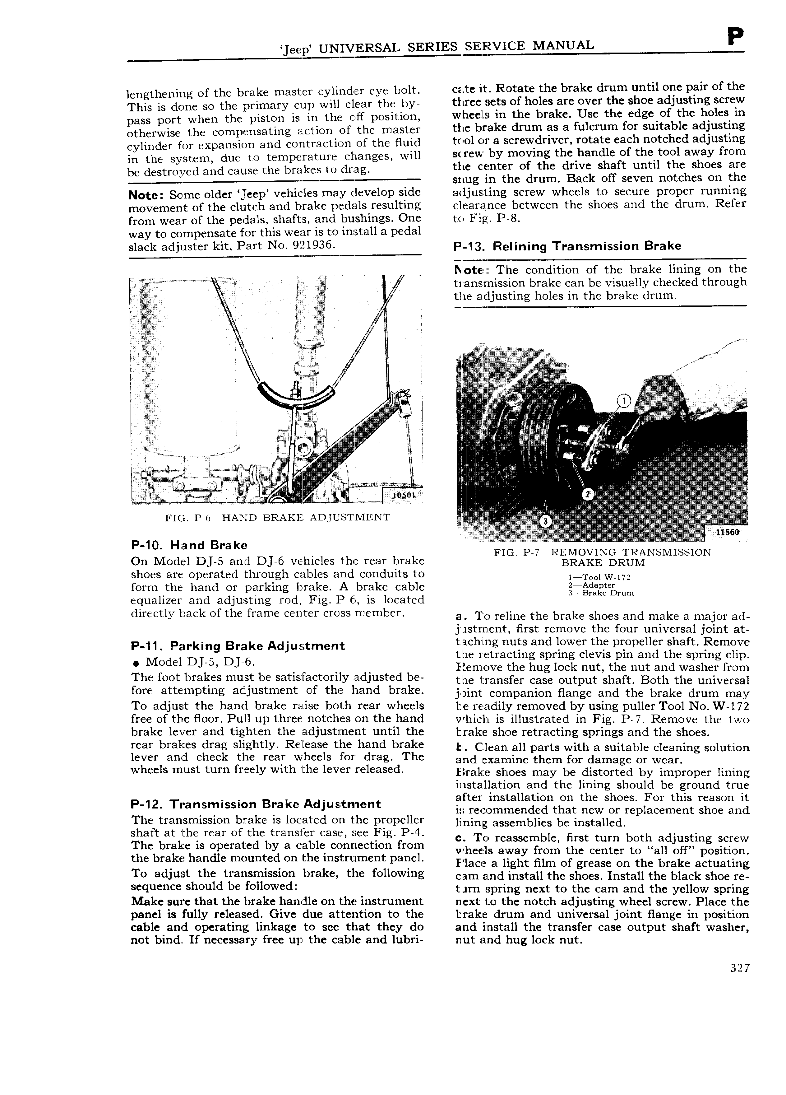
eep UNIVERSAL SERIES MANUAL P lengthening of the brake master cylinder eye bolt cate it Rotate the brake drum until one pair of the This is done so the primary cup will clear the by tlriircee sets of holes are over the shoe adjusting screw pass port when the piston is in the off position w hc e ls in the brake Use the edge of the holes in otherwise the compensating action of the master the bralke drum as a fulcrurn for suitable adjusting cylinder for expansion and contraction of the fluid t Zi C l OT Zi SCf wdf1ver rotate each notched adjusting in the system due to temperature changes will S i l W by moving thelhandle of the tool away from be destroyed and cause the brakes to drag tlZ l E C I of the dr1ve shaft until the shoes are S l L1 g in the drum Back off seven notches on the Note Some older eep vehicles may develop side a djust ing screw wheels to secure proper running movement of the clutch and brake pedalseresulting clearance between the shoes and the drum Refer from wear of the pedals shafts and bushings One to Fig P 8 way to compensate for this wear is to install a pedal Slack adiystsf km Part N0 9fyQ F 13 Rsiining Transmission Brake WW Mmmm j N 1l ee The condition of the brake lining on the TT i V K tZ 23 1I lEll IlllSSlOf1 brake can be visually checked through f the adjusting holes in the brake drum f lee T I lc Si ye J ex rs e I e i ii rf l l l i or i ii l l i Q ll ili M i i i i i 1 i al V Q s V l i i gint s W l is l l i l W WM V i j l A Q Q V l 2 1 E I ii 2Z E li i l v i Z i if I l I i l A Kii i A I Z i il I ln l 3 2 riZ E l Zi liZ i W i i 9 ii me as HAND BRAKE Apjusrmem Z 1 i i l 3 r i i i 3 11S60 P 10 d ke V On Model DJ 5 and Dj 6 vehicles the rear brake FIG PA7 nR l 2 N RTURL2NSMISSION shoes are operated through cables and conduits to l TO0lW 172 form the hand or parking lrirake A brake cable 2 Ad equalizer and adjusting rod Fig P 6 is located 3 Bia D m directly back of the frame center cross member EIM To feline the brake shoes and make a major ad j us I rne nt first remove the four universal joint at p 1 parking Brake Adjusitmemt taclhlng nuts and lower the propeller shaft Remove MO d C1 DLS DJ 6 the retracting spring clevis pin and the spring clip Iileimc the h l k t th t grhc logliibra fes mlljsl be SerlSla OEl iadJ lSted be the 1 ii fisfer cal giitpniilc sha ftl1ll3c clldtlllv lli11 fv l i1Il Om a Emp mg a lustment t larld brake joint companion flange and the brake drum may To adjust the hand brake raise both rear wheels be steadily removed by using puller Tool No W l72 free of the floor Pull up three notches on the hand which is ill r ust ated in Fig P 7 Remove the two brakeD leyer and tighlien tl iiacljustignergc ugtil the brake shoe retracting springs and the shoes rear ra es rag sig ty elease tue an brake bn Cj a 11 t th lever and check the rear wheels for drag The Ellmji B 2 l 2 l gr disjggilgf 5 lmg Solutlon Wheels must turn llreely Wlrll illle lever released Iiflzralscg shoes may be distorted by improper lining iixista ation and the lining should be ground true P 12 Transmission Brake Adjustmeriit ilflilil iE nt t jlhe Sh S fm this rieserl lt Iii 2 glgittgillfylsslonogrgge gs l j at d ell the grepillir lining assemblies be inslfclalllildrep acemcnt S Oc and e rear e rans er case see ig The brake is operated by a cable connection from ch r assci lblc Hlist tum bong adlusgmg ecfcw the brake handle mounted on the instrument panel V l 1l S away mm t C center tc all Off p sm TO ad w t the transmission bmk tl F H I lace a light film of grease on the brake actuating S J h ld b f H d l e le 0 Owlrlg czam and install the shoes Install the black shoe re qu S Ou C O OW tulzrzn spring next to the cam and the yellow spring Make sure that the brake handle on the instrument next to the notch adjusting wheel screw Place the panel is fully released Give due at tent1on to the brake drum and universal joint flange in position giblaiggidlgpuerating l1 lk8gC toh see ttiiat tgieybdo and irnsltall the transfer case output shaft washer ecessary ree up e ca e an u ri riut aim hug lock nut 327

 Next
Next