Ford Parts Wiki | GM Parts Wiki
Home | Search | Browse | Marketplace | Messages | FAQ | Guest
Prev

 Next
Next
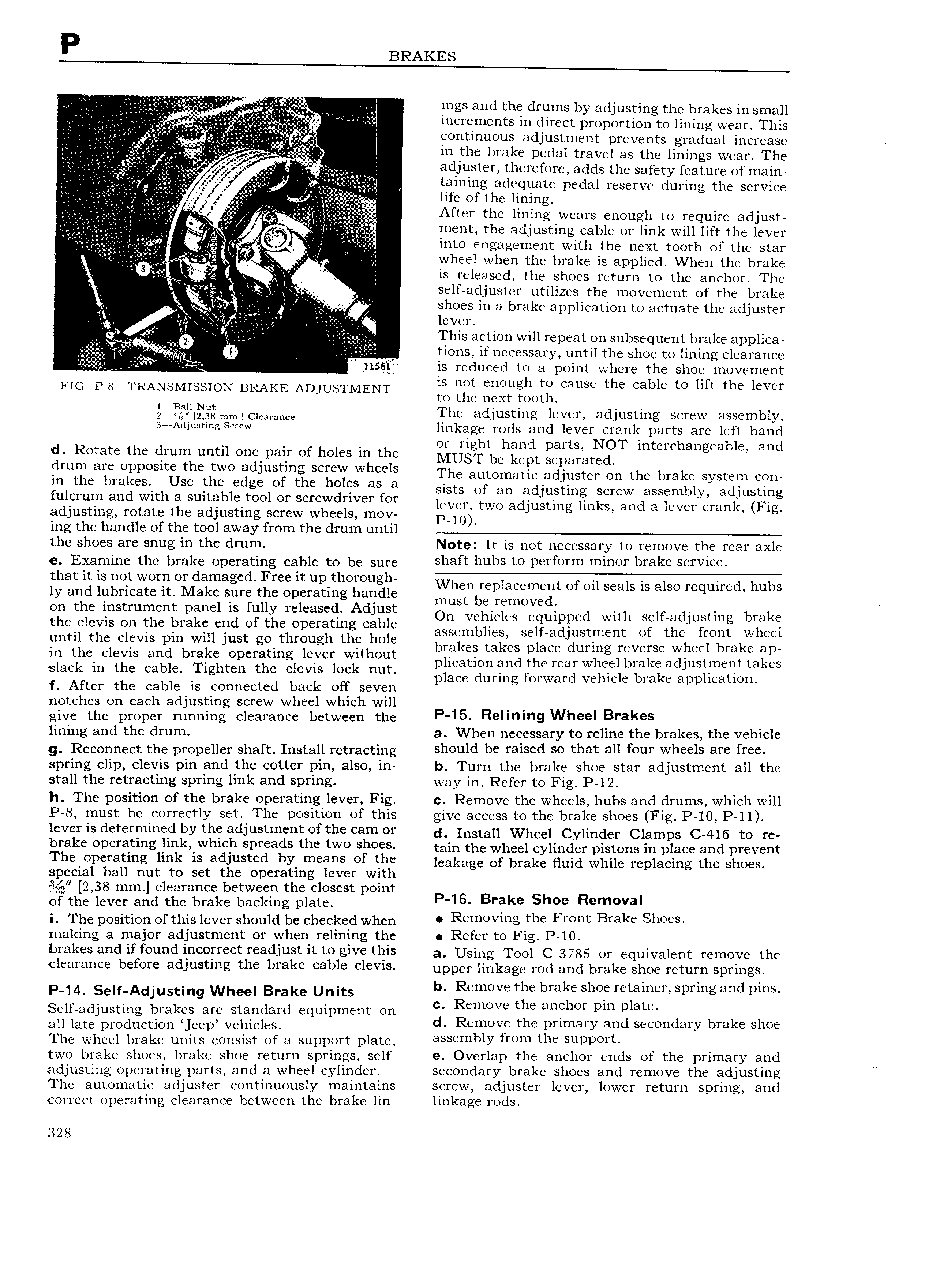
P BRAKES O V V A V E ings and the drums by adjusting the brakes in small Innz l jg increments in direct proportion to lining wear This r V ii Avgn r continuous adjustment prevents gradual increase j In th b k d I fag i i F3 e De a travel as the linings wear The i lg i i pit iY ggig V V pVpA AVA Vg VA atljtrster therefore adds the safety feature of main 4 I V i f i 1 E taining adequate pedal reserve during the service I i 1 v l hfc Of the lining I After the lining wears enough to require adjust O A i j f Q iez f ment the adjusting cable or link will lift the lever q O into engagement with the next tooth of the star i t V e Q i wheel when the brake is applied When the brake I is released the shoes return to the anchor The 5 V r A Self adjuster utilizes the movement of the brake 3 if i hO in 8 bfake application to aetuate the adjuster vk t tt E r j j This 3CtiOI 1 will repeat on subsequent brake applica V V ji V 0 I t V E tions if necessary until the shoe to lining clearance V r 1155l is reduced to a point where the shoe movement FIG P 8O TRANSMISSION BRAKE ADJUSTMENT pst enopgh 4 cause the cable to lift the lever e nex oo Qjjijlllfgg mm Clearance The adjusting lever adjusting screw assembly 3 rAdjusting serew linkage rods and lever crank parts are left hand d Rotate the drum until one pair of holes in the Z j g 1 h gt gt1 I T mt rcha g ab and Fguggcag Olgposltg thctgwo dJ tg g1ttLtr Wheels The automatic adjuster on the brake system con ra CS Se C e gc O C Ogg at 3 sists of an adjusting screw assembly adjusting ulcrum and with a suitable tool or screwdriver for 1 d k d 1 k ever two a justing lin s an a ever cran Fig adjusting rotate the adjusting screw wheels mov Pew ing the handle of the tool away from the drum until the shoes are snug in the drum Note It is not necessary to remove the rear axle e Examine the brake operating cable to be sure Shaft hubs to perferm miner brake Service that tt tt mit Wtttt Ot dtmegtd Fttt tt th t gh When replacement er en seals rr also required hubs ly and lubricate it Make sure the operat1ng handle must be removed on the instrument panel is fully released Adjust On Vehicles C ui ed with SCH 3d ustiug brake the clevis on the brake end of the operating cable q pp J assemblies selfadjustrnent of the front wheel until the clevis pin will just go through the hole brakes takes place during reverse wheel brake ap in the clevis and brake operating lever without 1 t dth T h lbrak adustment takes slack in the cable Tighten the clevis lock nut ply 1 foriwffd yeliile bmie spplication f After the cable is connected back off seven p g i notches on each adjusting screw wheel which will give the proper running clearance between the P 15 R mm9 Wheel Brakes lining and the drum a When necessary to reline the brakes the vehicle g Reconnect the propeller shaft Install retracting should be 1 3iS d S0 that QU OUT wheels 81 fcc spring clip clevis pin and the cotter pin also in b Turn the brake shoe star adjustment all the stall the retracting spring link and spring way in Refer to Fig P 12 h The position of the brake operating lever Fig c Remove the wheels hubs and drums which will P 8 must be correctly set The position of this give access to the brake shoes Fig P 10 P 11 lever is determined by the adjustment of the cam or d Instajj Wheel Cyjindcl Clamps C 4j6 tO rc brake OP Y tmg jmkywhmp Spreads thc two shO S tain the wheel cylinder pistons in place and prevent I h p r t g lmk is adiusted by t S f the leakage of brake nina while replacing the shoes special ball nut to set the operating lever with 2 38 mm clearance between the closest point of the lever and the brake backing plate P 16 Brake Shoe R m Va i The position of this lever should be checked when Removmg the Frtmt Brake ShO making a major adjustment or when relining the Refer to Fig P l0 brakes and if found incorrect readjust it to give this a Using TOO 3785 O1 equivalent YQOOOVO the Ci 3I 3I IC bCfOI C adjustlng the brake cable CICVIS upper linkage Od and brake Shoe return SpI ingS P 14 Sen AdjuSting Wheel Brake Units b Remove the brake shoe retainer spring and pins Self adjusting brakes are standard equipment on c Remove the th t pm plate ajj jam pmductiml J p V hiCj S d Remove the primary and secondary brake shoe The wheel brake units consist of a support plate aS mb Y mm th DDOYt two brake shoes brake shoe return springs self e Overlap the anchor ends of the primary and 7 adjusting operating parts and a wheel cylinder secondary brake shoes and remove the adjusting in The automatic adjuster continuously maintains screw adjuster lever lower return spring and correct operating clearance between the brake lin linkage rods 328

 Next
Next