Ford Parts Wiki | GM Parts Wiki
Home | Search | Browse | Marketplace | Messages | FAQ | Guest
Prev

 Next
Next
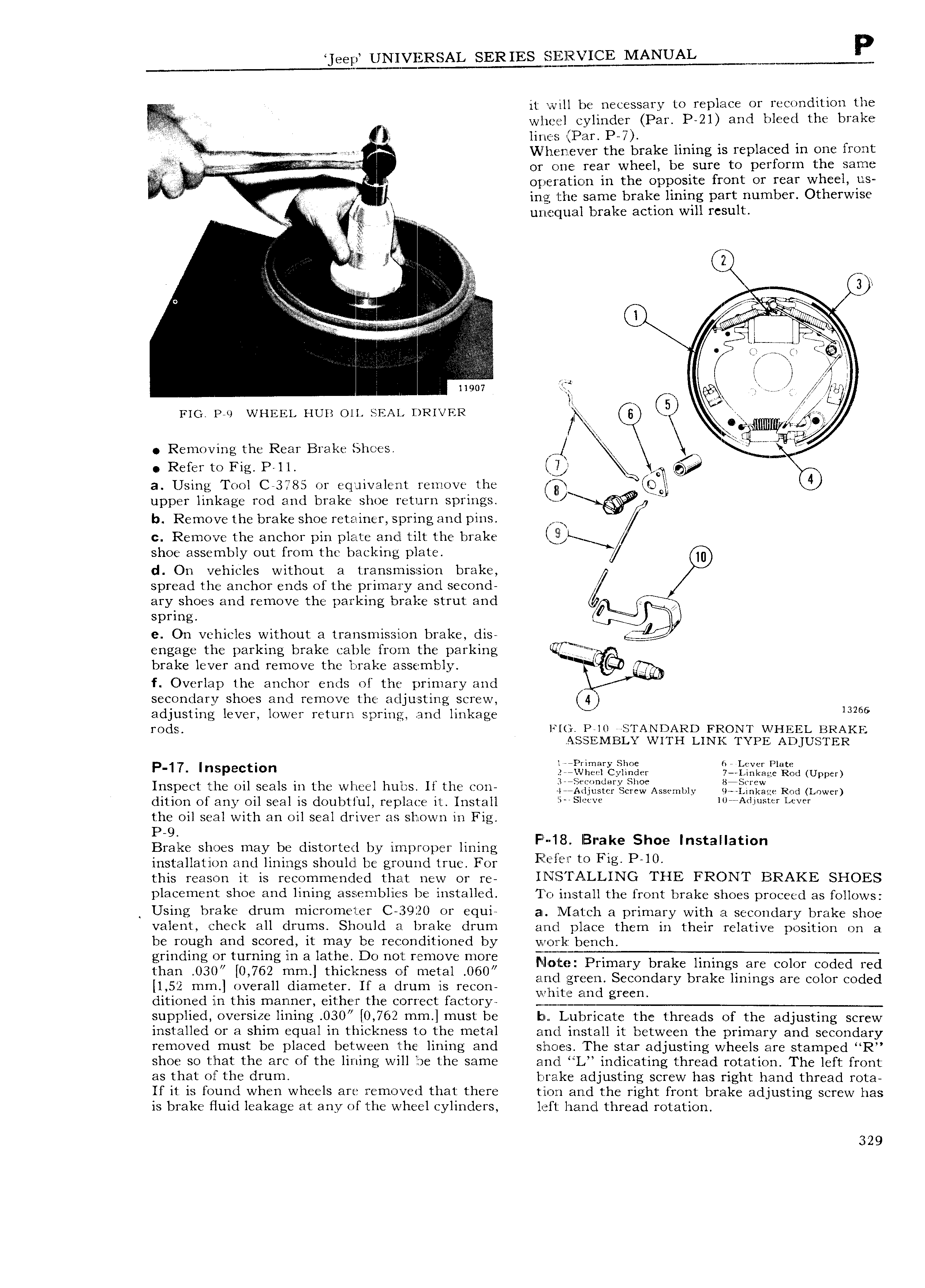
eep UNIVERSAL SERIES MANUAL W m H it will be necessary to replace or recondition the wlieel cylinder Par P 21 and bleed the brake T xiii Fs lines Par PY j N li enev er the brake lining is replaced in one front V e i or one rear wheel be sure to perform the same y operation in the opposite front or rear wheel llrS l V ing the same brake lining part number Otherwise in I I L11Zil EC ZZ l113 l brake action will result RI Q A its 3 Q V O V i i af l i i r f Ry l p l l 11907 EQ r i i jg l rj FIG P L WHEEL HUB Oll SEAL DRIVER 6 C5 Y l y krI A Wr Removing the Rear Brake Shoes x 4 Refer to Fig P ll Jl 3 6 D a Using Tool C 3785 or equivalent remove the jj 4 upper linkage rod and brake shoe return springs b Remove the brake shoe retainer spring and pins W c Remove the anchor pin plate and tilt the brake dl L shoe assembly out from the backing plate Q d On vehicles without a transmission brake spread the anchor ends of the primary and second ary shoes and remove the parking brake strut and e 4 spring e On vehicles without a transmission brake dis engage the parking brake cable from the parking UQC brake lever and remove the l ral e assembly l gplr f Overlap the anchor ends of the primary and I secondary shoes and remove the adjusting screw 4 adjusting lever lower return spring and linkage 13265 I OdS l P 10 STANDARD FRONT Vl HEEL BRAKE ASSEIVIBLY WITH LINK TYPE ADJUSTER P 17 Inspection li 3 3reSi t2 Xii f 1 2 i Upper Inspect the oil seals in the wheel hulis If the con illi2 Qi Q l E I AsS r 1y 3iiY Y Rod Lnwgr dition of any oil seal is doubtful replace it Install V l lmA i r I We the oil seal with an oil seal driver as shown in Fig P 9 ll Brake shoes may be distorted by improper lining F X 1 8 B a Shoe Installatlon installation and linings should be ground true For F f l E f to F1g PAO this reason it is recommended that new or re TNlf TALLTNG THE FRONT BRAKE SHOES placement shoe and lining assemblies be installed To install the front brake shoes proceed as follows Using brake drum micrometer C 3920 or equi an Match a primary with a secondary brake shoe valent check all drums Should a brake drum and place them in their relative position on a be rough and scored it may be reconditioned by va or l bench grinding or turning in a lathe Do not remove more F i figQ f i f tim 3 we mel t i t 5S f mee D60 2 i T i2 J32 Y bliilifgii E C C O i l 1 52 mm overall diameter If a drum is recon wmv rmd green ditioned in this manner either the correct factory Q j i supplied oversize lining 030 0 762 mm must be t n Lubricate the threads of the adjusting screw installed or a shim equal in thickness t o the metal and install it between the primary and secondary removed must be placed between the lining and shoes The star adjusting wheels are stamped R shoe so that the arc of the lining will be the same and L indicating thread rotation The left front as that or the drum brake adjusting screw has right hand thread rota If it is found when wheels are removed that there tion and the right front brake adjusting screw has is brake fluid leakage at any ofthe wheel cylinders left hand thread rotation 329

 Next
Next