Ford Parts Wiki | GM Parts Wiki
Home | Search | Browse | Marketplace | Messages | FAQ | Guest
Prev

 Next
Next
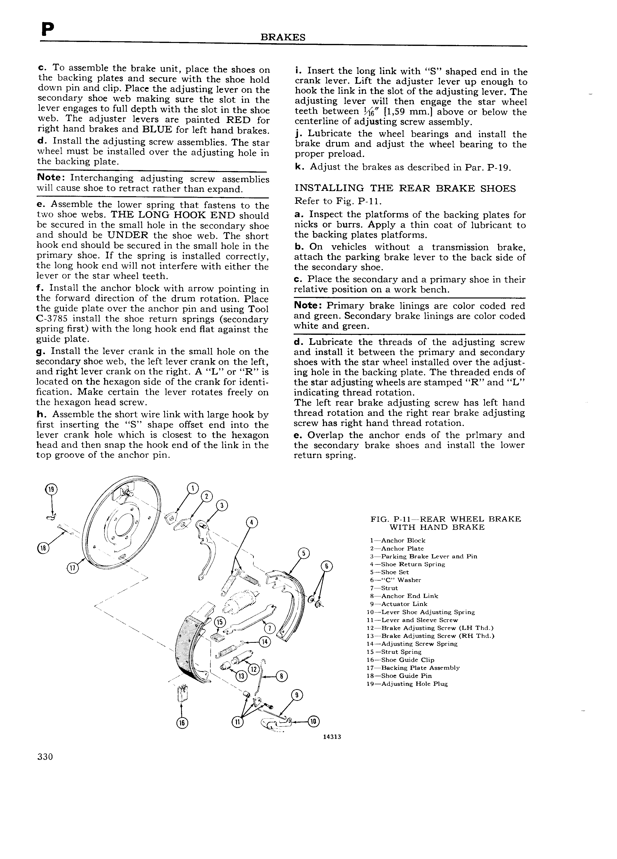
P BRAKES c To assemble the brake unit place the shoes on i Insert the long link with S shaped end in the the backing plates and secure with the shoe hold crank lever Lift the adjuster lever up enough to down pin and clip Place the adjusting lever on the hook the link in the slot of the adjusting lever The secondary shoe web making sure the slot in the adjusting lever will then engage the star wheel lever engages to full depth with the slot in the shoe teeth between 1 59 mm above or below the web The adjuster levers are painted RED for centerline of adjusting screw assembly rrght hahd brakes ahd BLUE for loft hahd brakeS j Lubricate the wheel bearings and install the d Install the adjusting screw assemblies The star brake drum and adjust the wheel bearing to the wheel must be installed over the adjusting hole in proper preload tho backing plate k Adjust the brakes as described in Par P 19 Note Interchanging adjusting screw assemblies will cause shoe to retract rather than expand INSTALLING THE REAR BRAKE SHOES e Assemble the lower spring that fastens to the Refer to F1g P H two shoe webs THE LONG HOOK END eheuid a Inspect tho platforms of tho baokmg platss for be secured in the small hole in the secondary shoe hleks 0r burrS APPIY a thm eeat of luhrreaht to end should be UNDER the shoe web The short tho baokmg platos platforms hook end should be secured in the small hole in the b On vehicles without a transmission brake primary shoe If the spring is installed correctly attach the parking brake lever to the back side of the long hook end will not interfere with either the the secondary shoe leVer or the stat Wheel teeth c Place the secondary and a primary shoe in their f Install the anchor block with arrow pointing in relative position on a work bench the forward direction of the drum rotation Place the guide plate over the anchor pin and using Tool d rm ary dm bm1 ngF are CO or CE maid C 3785 install the shoe return springs secondary ar l tgrc 3 econ ary ra c mmgs are CO C spring first with the long hook end flat against the W 1 c an green guido Plate d Lubricate the threads of the adjusting screw g Install the lever crank in the small hole on the and install it between the primary and secondary secondary shoe web the left lever crank on the left shoes with the star wheel installed over the adjust and right lever crank on the right A L or R is ing hole in the backing plate The threaded ends of located on the hexagon side of the crank for identi the star adjusting wheels are stamped R and L fication Make certain the lever rotates freely on indicating thread rotation the hexagon head screw The left rear brake adjusting screw has left hand h Assemble the short wire link with large hook by thread Yetatleh and tho fight realf brake adJu tlhg hrst inserting the S shape offset end into the Screw has right hahd thread retatrerr lever crank hole which is closest to the hexagon e Overlap the anchor ends of the prlmary and head and then snap the hook end of the link in the the secondary brake shoes and install the lower top groove of the anchor pin return spring Q j r W K l W g FIG 1 1ia REAR WHEEL BRAKE T QJ WITH HAND BRAKE wir a J 1 Anchor Block 0 a i hr i 2 Anchor Plate L d PV y N 3 Parking Bra e ever an in L 4 Shoe Re urn S rin are r ye 5 Shoe Sett P g Z ga 6 C Washer Q i S ru ide A 3 gfpiieiier End Link a fL r r iL 9 Actuat0r Link E lO4 Levcr Shoe Adjusting Spring Lever and Sleev Screw 9 pl x D l Brake Adjusting Screw LH Thd K il A Z F U 13 Brake Adjusting Screw RH Thd xyjgr m i 14 Adjusting Screw Spring N I x l 5 I5 StrutS rin 4 I ieashee ciadegclip We 17 Backing Plate Assembly 8 sh G id Pm fI6 n jc 6 ig Aeiiieeaiig iieie Plug liu 9 o to ii 14313 330

 Next
Next