Ford Parts Wiki | GM Parts Wiki
Home | Search | Browse | Marketplace | Messages | FAQ | Guest
Prev

 Next
Next
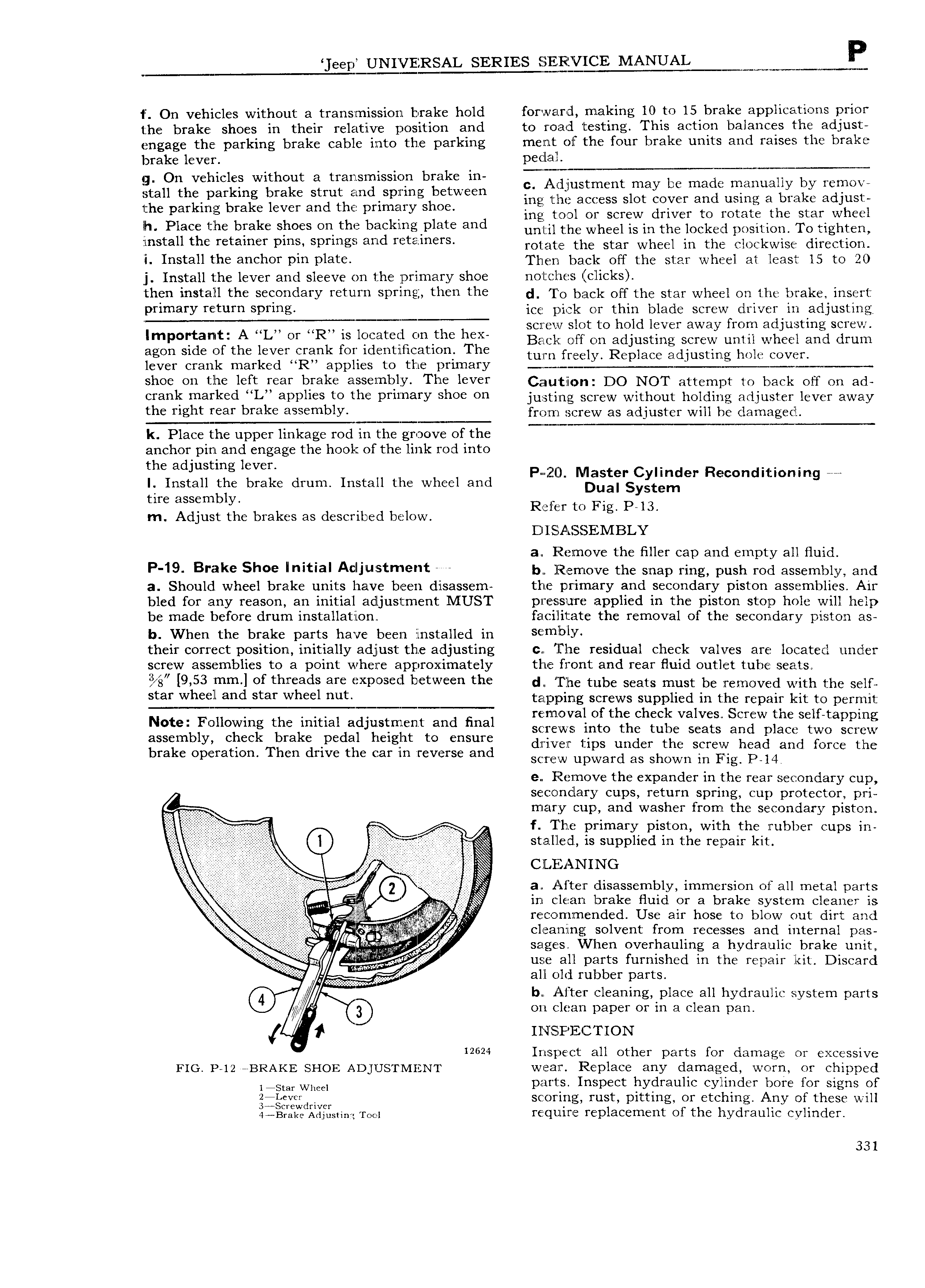
eep UNIVERSAL SERIES MANUAL W wm H 1 On vehicles without a translmission brake hold forwar d making 10 to l5 brake applications prior the brake shoes in their relative position and to road testing This action balances the adjust engage the parking brake cable into th e parking ment of th e four brake units and raises the brake brake lever pedal g On vehicles without a transmission brake in iT I r I vg ssh hhs hsrhhs hehe shut sheshhhs hhhshh i llll l Z2i2t i aZOEE Ei l u 2Ei 2 lL Z 3 L 2Z the parking brake lever and the primary shoe gh ing tool O1 screw driver to rotate the star wheel lh Plsss the hrsks shsss sh this h sshlhs elsts and mir the wheel is in the rocked saloon To sigma install the retainer pmS Sprmgil md mt m rS rotate the star wheel in the clockwise direction I Install the anchor pin plate Then back off the star wheel at least 15 to 20 j Install the lever and sleeve on the primary shoe no l ches clicks then l t llll the S OYld3l Y Y tU l ll DYl Z tl e the d To back off the star wheel on the brake insert Pflmary Y tuY PYl ice pick or thin blade screw driver in adjusting A N M screw slot to hold lever away from adjusting screw lmp lltan A L sr Rk ES l Ht iil On th Baclr off on adjusting screw until wheel and drum agO Sldc O hhs leveffr fl Ol 1d nt lHCatlO J C turn freely Replace adjusting hole cover lever crank marked R applies to the primary M shoe err tlle left rear brake assemlqly The lever c Iu tl n DO NOT attempt to back on on an Cfanlf mafkcd L aPPll te the Pflmaly hO OU ju stin g screw without holding adjuster lever away the rrsht Y 3l brake 9 mblY from screw as adjuster will be damaged k Place the upper linkage rod in the groove of the M anchor pin and engage the hool of the link rod into the adjusting lever P ill M t C I Re we I Install the brake drum Install the wheel and Tg ytgsger Econdllmmng tire assembly a ys I i Refs t F P l3 m Adjust the brakes as described below Y O lg D l SLASSEM BLY al Remove the filler cap and empty all fluid P 19 B iik 66 lmtlal Adl1ll l5tm t r r b liiernove the snap ring push rod assembly and a Should wheel brake units have been disassem the primary and secondary piston assemblies Air bled for any reason an initial adjustment MUST pressure applied in the piston stop hole will help be made before drum installation facilitate the removal of the secondar iston as V Y P b When the brake parts have been installed in S mlblY their correct position initially adjust the adjusting c The residual check valves are located under screw assemblies to a point where approximately the front and rear fluid outlet tube seats xl X A 98 9 53 mm ef threads are r se l between the d rlie tube seats must be removed with the Serra star Whe l and stsr Wheel nut tapping screws supplied in the repair kit to permit Note Following the initial adjustment and final r lllmlO V al Of the h k Valves Screw the Sclftappmg screws into the tube seats and place two screw assembly check brake pedal height to ensure 1 d h brake O t Th d tl J d river ips un er t c screw head and force the pera ion en rive ie car in reverse an SCIFW upward as shown m Fig PJ4 e Remove the expander in the rear secondary cup secondary cups return spring cup protector pri M EE E mary cup and washer from the secondary piston f T h e primary piston with the rubber cups in g gg Jl r 2 jg j Q stalY ed is supplied in the repair kit r f I j 5 f1i I Q Ij E i3 2Yf Q I 5 i fe V j ff EVEgi g I l E r l 3 tll ll t F disassembly immersion of all metal partg 5 in clean brake fluid or a brake system cleaner is 2 5 E 3 ta yM Ml jl l w i reconiimended Use air hose to blow out dirt and h s lllllll 1lh ll sslveht fthm recesses shd hrterhsl has ss g g g g g Fw V r WH w sages VI hen overhauling a hydraulic brake unit 5 g l l ll Iwl as le r E I f use all parts furnished in the reoair kit Discard s VV i A4 all old rubber parts b Alter cleaning place all hydraulic system parts 3 on clean paper or in a clean pan 4 1 IlI l SPEC I ION 12624 Inspect all other parts for damage or excessive FIG P 12 hBRAKE SHOE ADJUSTMENT wear Replace any damaged worn or chipped lism Wheel parts Inspect hydraulic cylinder bore for signs of giggygzrdrivcr scoring rust pitting or etching Any of these will 4 Brake Adjusting rear require replacement of the hydraulic cylinder 331

 Next
Next