Ford Parts Wiki | GM Parts Wiki
Home | Search | Browse | Marketplace | Messages | FAQ | Guest
Prev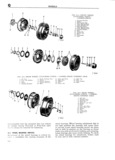
 Next
Next
eep UNIVERSAL SERIES MANUAL Q 0 C2 3 l l if T l YFF Q in j if i FIG Q 5 REAR WHEEL gig A ti Q5 AT I ACHl NG PARTS it ii if i F LANGED AXLE l ji if gp l Brake Backing Plate gr 2 Retainer Ring v il j j 3 Unit Bearing A i i i a x i Vi g Stal gr t S Retainer Plate x iii r fc i l 6 Br k Drum l v i 7 cup Plug 5 8 Flang ed Axle Shaft I i Qll fj M a 0 fh iiii r I Q 4 Checking Front Wheel Bearings ti 1lirr 1 making sure that wheel rotates freely without Raise the front end of the vehicle with a jack fEE 2 QSh3k so that the tires clear the floor R 1 th i k hi d i k t B d Grip the tire and test sidewise shake of the wheel erlizgligck gvasfer S Us an OC ml en If bearings are correctly adjusted shake of the f ti k th d t t P 4 R H wheel will be just perceptible and wheel will turn lic 8 3 Jus men al Q easslim l 6 freeiy with no drag t ledriving flange and hub cap Make certain the If bearing adjustment is too tight the rollers may ls PYOPEFIY mstalled between the hub and break or become overheated Loose bearings may l E allg cause excessive wear and noise 0 lM odlel D 5 D 6 If this test indicates bearing adjustment is neces Can t wO Whee drive Vehicles rerneve the hub can saryi follow tho procedure grvori rn Parr Q 5 Looso and the wheel retaining nut eetter pin Rotate the bearings will cause sidewise shake that is evident vg gg and tighten the wheel retaining nut until around th t i 1 mf t il 0f th Wh l A the wheel binds Then back off nut about one sixth h6k that is ovrdont 0 lY Whoo gjtiplilmli th Wil l tl l l l or more if necessary making sure wheel ro in a plane parallellto the ground but Hot f1d t tates freely without sidewise shake Replace the around the entire circumference probably indicates C i i er pin end huh een looseness in the steering linkage Cllr 6 Reanr Wheel Bearing Adjustment Q 5 Front Wheel Bearing Adjustment Flange Ax e Shafi With the vehicle on the jack the following prOC i el licles equipped with the flange type rear axle dure should be followed to adjust the front wheel sjliazft require no wheel bearing adjustment The beatings 0 f0 f Wh l dfiV V l1iCl S flanged axle shaft is equipped with a single row a Remove the hub cap snap ring capscrews and pre adjusted tapered roller unit bearing capable of washers that attach the driving illange to the hub aicceptiingg thrust in either direction The unit b Using the Front Axle Shaft Drive Flange Puller j3 E 9U S adjustment 1S b lt W at the factory mak W 63 pull the driving iciaiige 11iig s ll11111m1ng or bearing adjustment unnecessary c Bend the lip of the nut lock washer so that the lilllllel to Flg Q 6 locknut and lock washer may be removed G 7 Checking Rear Wheel B aringS d Rotate the wheel and tiglhtezn the adjustment apered Axle l h h M MM Fillaise wheel on which adjustment is to be made Note Front tire and wheel must be rotated by by placing a jack under the axle housing With hand as the adjusting nut is tightened to ensure hands test sidewise shake and in and out play positive seating of the bearing of the wheel If bearings are correctly adjusted Then back off the adjusting nut about one sixth shake of wheel will be just perceptible and the 337