Ford Parts Wiki | GM Parts Wiki
Home | Search | Browse | Marketplace | Messages | FAQ | Guest
Prev

 Next
Next
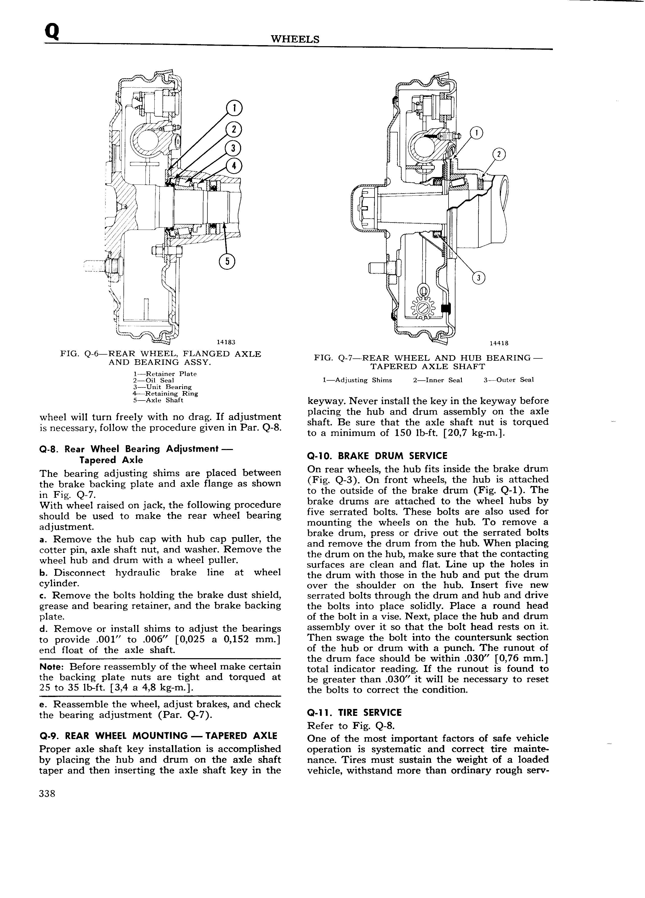
WHEELS u er F rare EE Wil in ass Tl 1 I II 0 1re1 o ti qu I r Ib J In l Q i IIt T a A 9 I g Op K1 a n 3 I 1 rv 1 i W z M I I j e ilf Z I Ifll II r um ji g K 5 2 EQ 1 ll 1 ia 1 1 EI gl annlll a t 0 1 H N lr ea 7 ire 5 It r i 14183 M 14418 FIG Q 6 REAR WHEEM FLANGED AXLE FIG Q 7 REAR WHEEL AND HUB BEARING AND BEARTNG SSY TAPERED AXLE SHAFT gigiii eggaigie l Adjusting Shims 2 Inner Seal 3 Outcr Seal 5 A t m f mg keyway Never install the key in the keyway before placing the hub and drum assembly on the axle wheel wm tum freely Wlth no drag It Rdlustmem shaft Be sure that the axle shaft nut is torqued IS necessary follow the procedure given in Par Q 8 to 3 minimum of 150 lb ft 20 7 kg m 8 R Wh IB Ad t t Q faperjg Af g S me o 10 BRAKE lDRUMhS R ICF d h b k d The bearing adjusting shims are placed between Ott tear Whee S the u Its msi Q t 6 m B mm the brake backing plate and axle flange as shown 32 fn gtggt t lS k 1 1SQ a in Fig Q 7 bo ke du S1 B 2 attach de to the whiel hubs b With wheel raised on jack the following procedure Fra E rum S T Th 8 b I I d f y should be used to make the rear wheel bearing We Sgrratih egs I gig th timage iiosorgiizve C Zdjgiilnj lg the hub Cap with hub cap puller the gi ll Ie l rR1m p1i ss i drive out the serrated bolts and remove the drum from the hub When placing Colftei EH ax Shaft mlhland aSP r 1F mOV the the drum on the hub make sure that the contacting W 9 u aa rum Wl a W ee Pu BI surfaces are clean and flat Line up the holes in b D se eet hydrauhe brake e at Wheel the drum with those m the hub and pur rhd drum CYImdeI over the shoulder on the hub Insert five new c Remove the bolts holding the brake dust Shield serrated bolts through the drum and hub and drive grease and bearing retainer and the brake backing the bolts into place solidly Place a round head plate of the bolt in a vise Next place the hub and drum d Remove or install shims to adjust the bearings assembly over It 0 tI at the belt head rests 0 It tc provide 00 to 005 0 025 a 0 152 mm Then swage the bolt into the countersunk section end addr of the axle shaft 0 tlgie hut er dlgunadw th a 1 5r ei63 3Fh i0r t ei t e rum ace s ou e wit in mm N e Befere reassembly ef the wheel make eertam total indicator reading rr the ruhuur is found to the beckmg PI3te nuts are tight and totqued at be greater than 030 it will be necessary to reset 25 te 35 Ib tt l3 4 8 4 8 kg m l the bolts to correct the condition e Reassemble the wheel adjust brakes and check the bearing adjustment Par Q 7 Q II TIRE SERVICE Refer to Fig Q 8 Q 9 REAR WHEEL MOUNTING IAPERED AXLE One of the most important factors of safe vehicle Proper axle shaft key installation is accomplished operation is systematic and correct tire mainte by placing the hub and drum on the axle shaft nance Tires must sustain the weight of a loaded taper and then inserting the axle shaft key in the vehicle withstand more than ordinary rough serv 338

 Next
Next