Ford Parts Wiki | GM Parts Wiki
Home | Search | Browse
Prev
 Next
Next
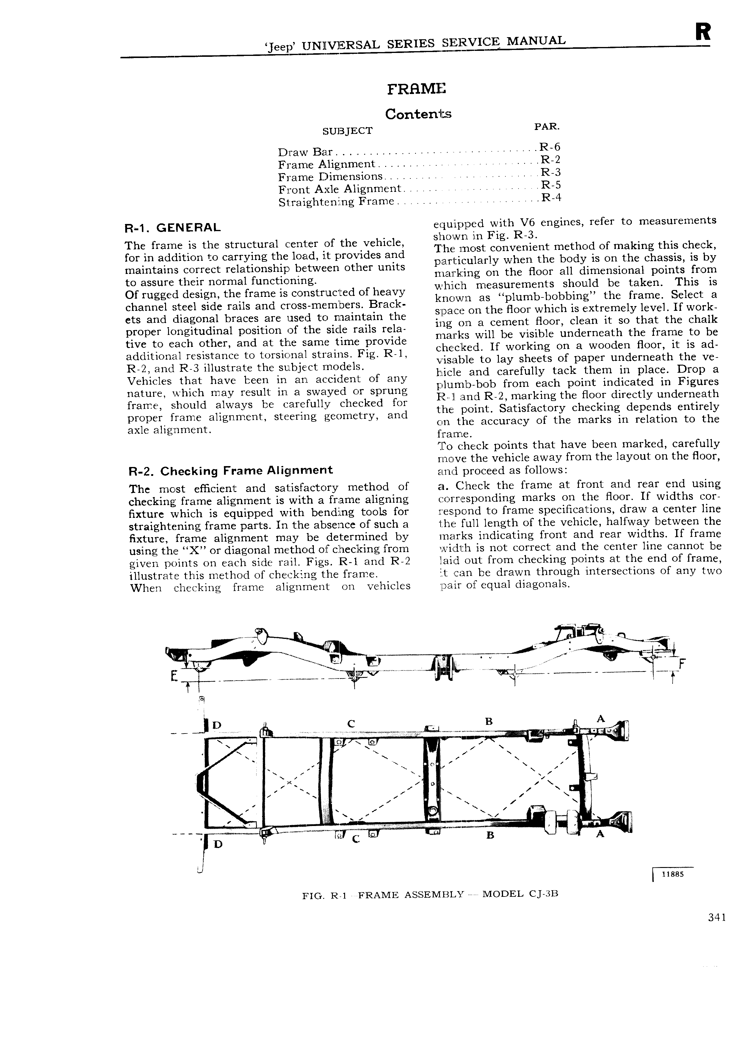
eep UNl VlERSAL SERIES SERVICE MANUAL R FRHMIEEZ Contents SUBJECT PAR Draw Bar U 4 R 6 Frame Alignment U V U U U R 2 Frame Dimensions U U U U R 3 Front Axle Alignment U U U U UR 5 S1raighten ng Frame U U U U R 4 R 1 GENERAL equipped with V6 engines refer to measurements The frame is the structural center of the vehicle mcthcid Of making this chepk for in addition to carrying the load i t provides and j U particularly when the body is on the chassis is by maintains correct relationship between other units mm k ing On the BOOT an dimensional points from to assure their normal functioning I Z l t li Th Of rugged design the frame is constructed of heavy E mich r aiu i ni LSOb Ui g tz filarilg Sclgit 1 channel steel side rails and cross members Brack jmmim H ih OOr hich is Ejxtmmcl hive If WO k ets and diagonal braces are used to maintain the P E l cm nt gOO1 clel n it Soythat he Chalk proper longitudinal position of the sicle rails rela ailicb e isiblc imd rncath the frame to be tive to each other and at the same time provide rl 1 fl EV If O kin On a WOOdc BOOT it is ad additional resistance to torsional strains Fig R 1 Cyleli UF 1 W She ti Of 3 er underncajih the V R 2 and R 3 illustrate the subject models Els e 3 2 une tackp glam in lace Dm ca Vehicles that have been in an accident of any MCC am C E y p I r plunilb bob from each point indicated in Figures nature Vi hlch may result m 3 Swdyed OY Sprung P ll and R 2 marking the floor directly underneath frame should always be carefully checked for i U proper frame alignment Steering geometry and the point Satisfactorky chccklgng depends entirely axle aligjnmcnn gin the accuracy of t e mar s in relation to the zrame To check points that have been marked carefully move the vehicle away from the layout on the floor R 2 Checkmg Frame Al 9 nm r t an l proceed as follows The most efficient and satisfactory method of aes Check the frame at front and rear end using checking frame alignment is with a frame aligning r 1 r esponding marks on the floor If widths cor fixture which is equipped with beznding tools for respond to frame specifications draw a center line straightening frame parts In the absence of such a lUhe full length of the vehicle halfway between the fixture frame alignment may be determined by irnarkzs indicating front and rear widths If frame using the X or diagonal method of checking from width is not correct and the center line cannot be given points on each side rail Figs R l and R 2 laid out from checking points at the end of frame illustrate this method of che U l ing the frame it can be drawn through intersections of any two When checking frame alignment on vehicles oair of equal diagonals l u e J Ey Ig i if A j If 4 g ii V i N W if V A F f g M j v c c on r r W al ts or WM 4 1 l 1 lj D c B A UU U e W M w i l W U U Xx O m r niln sxu g V V L 1 V r i fr i 1 i z i x I N L e l IF I U U F j I yl W T D B A g l ness FIG R 1 FRAME ASSEMIBIUUX ll IODEL CJ 3B 341