Ford Parts Wiki | GM Parts Wiki
Home | Search | Browse
Prev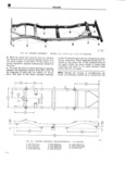
 Next
Next
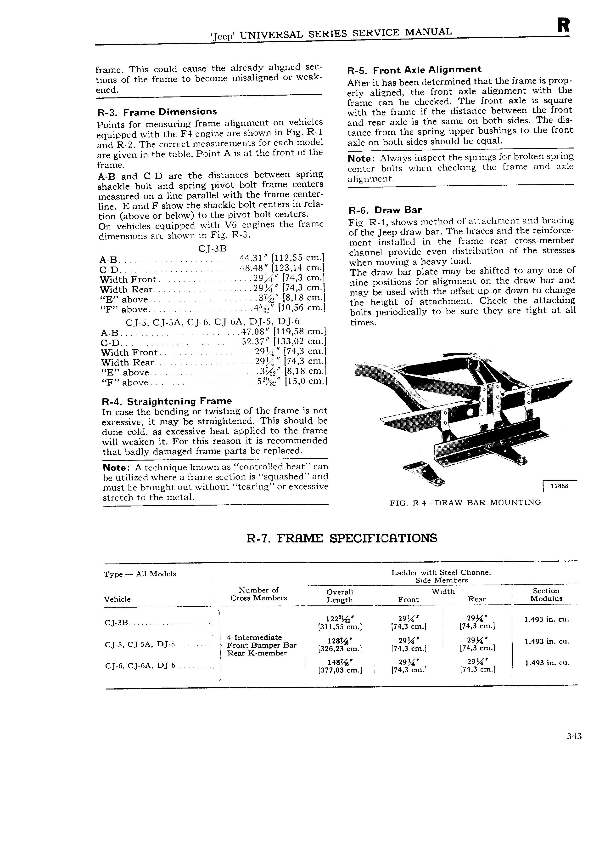
eep UNIVERSAL SERIES MANUAL R frame This could cause the already aligned sec R 5 Front Axle Alignment tions of the frame to become misaligned or weak cn d A I ter it has been determined that the frame is prop erly aligned the front axle alignment with the frzanie can be checked The front axle is square R 3 Frame D m s with the frame if the distance between the front P0i fS OY m 3S 1fi g fY3m H m 1T t QU V h l and rear axle is the same on both sides The dis Q iDD d with thi F4 gi M6 h0W m Fig RJ tance from the spring upper bushings to the front and R 2 The correct measurements for each model a j 1 on blyth Sides should be qu3l are given in the table Point A is at the front of the rama c e 1 ways inspec esprings or ro en spring A B and C D are the distances between spring Ciiifwilifil bjjts when Chcckmg the frame and axle shackle bolt and spring pivot bolt frame centers measured on a line parallel with the frame center line E and F show the shackle bolt centers in rela tion above or below to the pivot bolt centers F E Draw Ba On vehicles equipped with V16 engines the frame Fig R 4 shows method of attachment and bracing dimensions are shown in Fig R 3 o I the jeep draw bar The braces and the reinforce CJ 3B ment installed in the frame rear cross member A B h I 4 4 A A U 44 31 112 55 Cm clqalininell provideheven ldisgribution of the stresses c 1 4 s 4s 122 14 em 1 l ga Y O3 1 1 wl 1 lie draw bar plate may be shifted to any one of Width Front 2 14 4 3 cm Width Rear WVU 74 3 Cm nine positions for alignment on the draw bar and MEN abooc i ii i i 2572 1 8 8 Cm nnagjy be used with the offset up or down to change U H iii 321 the height of attachment Check the attaching F above 44 10 56 cm bolts periodically to be sure they are tight at all CJ 5 CJ SA CJ 6 CJ DA DJ 5i DJ 6 t i rne s A B 47 0a 119 58 em C D 52 37 133 02 cm Width Front 29 74 3 cm W Width Rear 29 74 3 cm H W st E above 3 8 18 em f F b 2 rI i A a C lc 5 32 15 0 Cm l 3 A 3 i R 4 Straightening Frame iiii A O Z In case the bending or twisting of the frame is not V 0 excessive it may be straightened This should be i 0 i 4 4 done cold as excessive heat applied to the frame f 2 Ji will weaken it For this reason it is recommended if that badly damaged frame parts be replaced inii Note A technique known as controlled heat can if 5 be utilized where a frame section is squashed and must be brought out without tearing or excessive V stretch to the metal 11888 FIG R 4 DRAW ELAR M0 UNT1NG R 7 FRHME SPE H llZFI C HTIONS TYPC All Models Ladder with Steel Channel T 4 mb rS Number of O U W dth T S 1 g j g V LZ h Front Rear ME l I W 1 T W cj an 122 29V 219 cnxlil 74 3 I 74l 3 1 493 lh CU 4 I t xd CJ 5 CJ SA DJ 5 1 1 E m f B 3 228 29 219 1 493i1 Hear Kmncmbcr 2 23 cn 1 74 3 cm 74 3 cm cys C 6A D 6 148 29 29 I 377 0s 1 1 74 3 im 74 3 im L493 m C 343