Ford Parts Wiki | GM Parts Wiki
Home | Search | Browse
Prev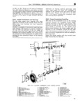
 Next
Next
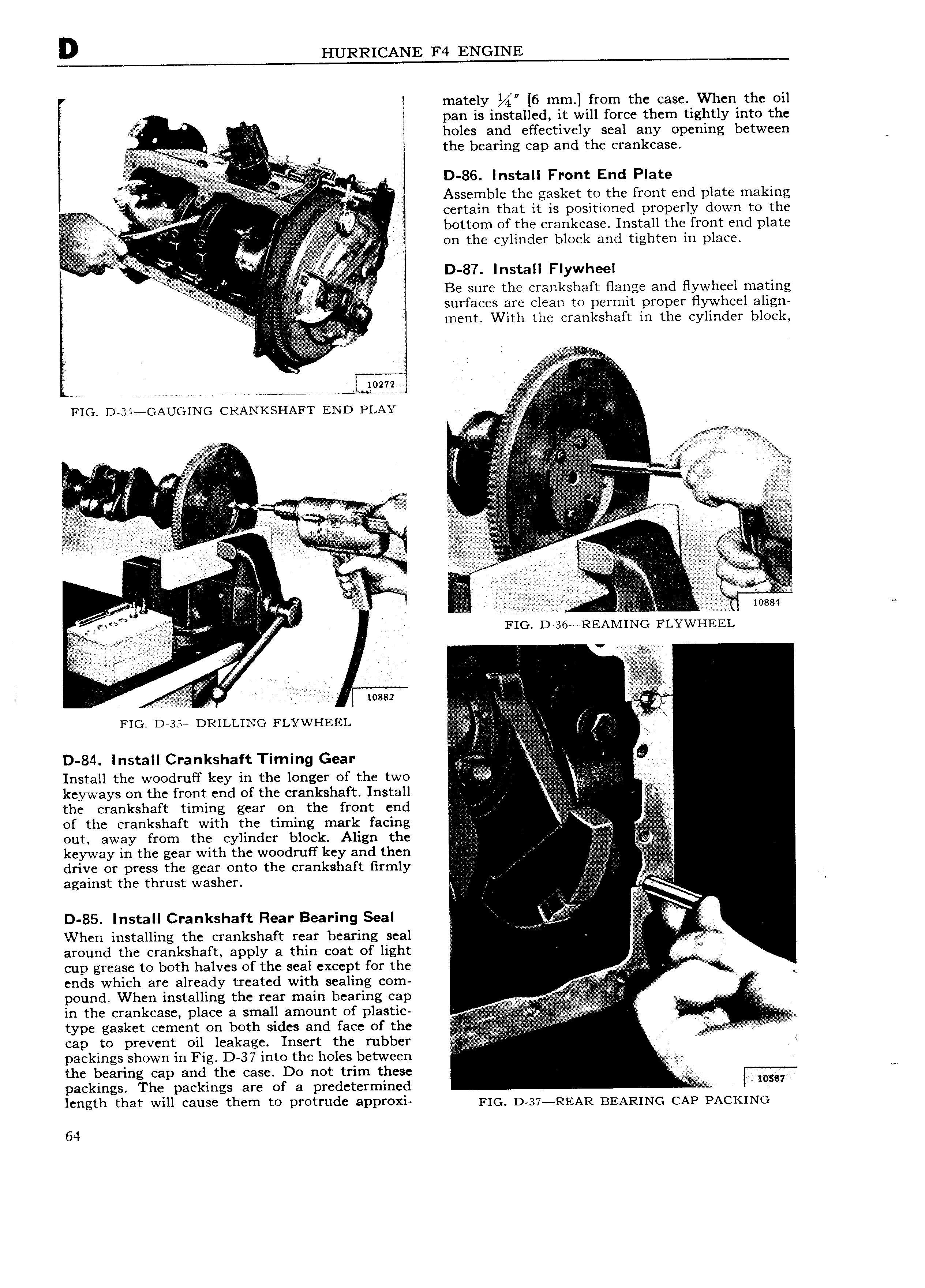
D HURRICANE F4 ENGINE F l mately 6 mm from the case When the oil X I pan is installed it will force them tightly into the af v I holes and effectively seal any opening between y g g the bearing cap and the crankcase i a I 2 raw Y I ii D 86 Install Front End Plate l I Ea an qi Assemble the gasket to the front end plate making I a Certain that it is positioned properly down to the ii gi V bottom of the crankcase Install the front end plate 4 I T on the cylinder block and tighten in place z ry I i e jj D 87 Install Flywheel A Be sure the crankshaft flange and flywheel mating f surfaces are clean to permit proper flywheel align ment With the crankshaft in the cylinder block I F FF Vr y l I l ii i iE v ga lF 7 i ff FIG D 3 fGAUG1NG CRANKSHAFT END PLAY l if niii X il lli r ei r I FR yV V t iiV ss is f i I izi i A ff l i ii III I II II I 3 ji III l I V I i FFjj F l V C V E z i z i F ni i i I r Yi Ei r yy y f Iii l g L g E v Z Z ngh B r a s x W V 5 IW l I if 5 iiiiiii FI F i IPT I l FIG D 36 REAMING FLYWHEEL ii iA I Q liiln if i iI W I y I I I Q W iossz l if V V 1 V V FIG D as e eee DRILLING FLYWHEEL g f F D 84 Install Crankshaft Timing Gear i 5 5 iI i jQV i J Install the woodruff key in the longer of the two I I3 keyways on the front end of the crankshaft Install I FF the crankshaft timing gear on the front end of the crankshaft with the timing mark facing I F out away from the cylinder block Align the keyway in the gear with the woodruff key and then drive or press the gear onto the crankshaft firmly I against the thrust washer 5 I I Fl I g I D 85 Install Crankshaft Rear Bearing Seal E zg V When installing the crankshaft rear bearing seal V a around the crankshaft apply a thin coat of light F cup grease to both halves of the seal except for the II I W ends which are already treated with sealing com in pound When installing the rear main bearing cap m i ii I iiiiz J in the crankcase place a small amount of plastic Zi I lnnr g V type gasket cement on both sides and face of the F I I N F l I cap to prevent oil leakage Insert the rubber I I I packings shown in Fig D 37 into the holes between the bearing cap and the case Do not trim these packings The packings are of a predetermined Y TiF l wsu length that will cause them to protrude approxi F1C D 37 REAR BEARING CAP PACKING 64