Ford Parts Wiki | GM Parts Wiki
Home | Search | Browse | Marketplace | Messages | FAQ | Guest
Prev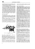
 Next
Next
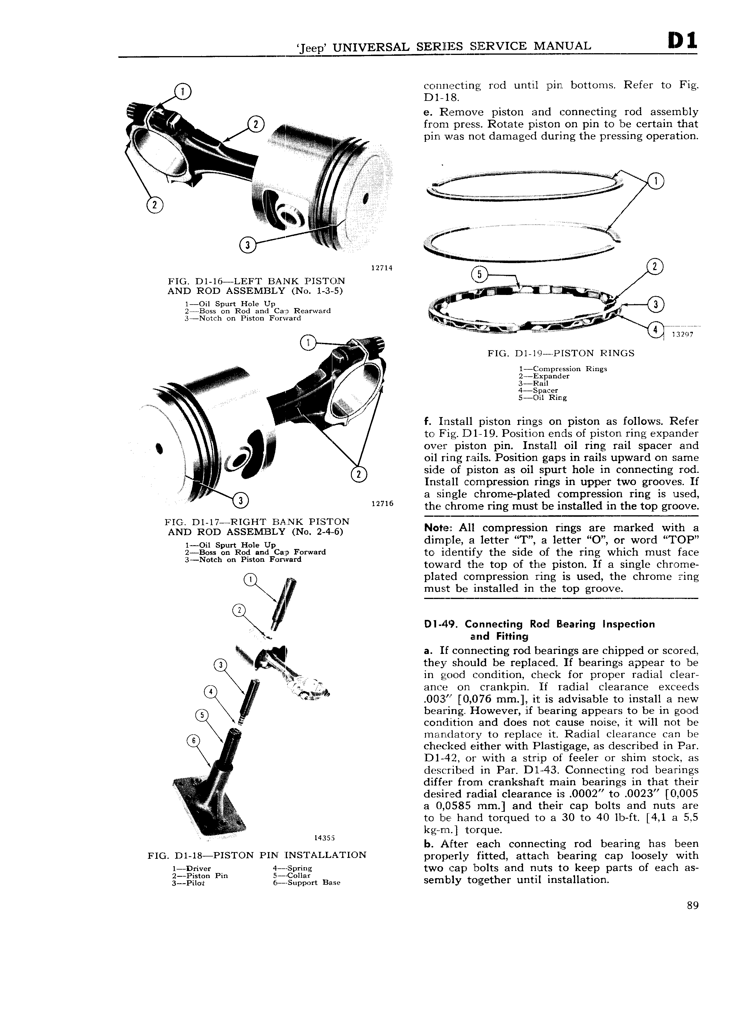
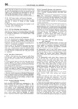
eep UNIVERSAL SERll ERVICE MANUAL H connecting rod until pin bottoms Refer to Fig Dl 18 I e Remove piston and connecting rod assembly from press Rotate piston on pin to lbe certain that in I 2 V pin was not damaged during the pressing operation E2 i fl V f i z K v Q z s r z Q5 2 f iii i g 12714 g FIG Dl l6 LEFT BANK PISTCIN J Sp MM W AND ROD ASSEMBLY No 1 3 5 iii l Oil Spurt Hole Upw i 24Boss on Rod and a J Rearward 3 Notch on Piston Forward ME cW 4 Q WWMM M V J v FIG Dl l 3 PISTON RINGS Rings 1 ii 1 S 1 4 V 2 L R 1 a i 1tr f Install piston rings on piston as follows Refer B to Fig D1 19 Position ends of piston ring expander li over piston pin Install oil ring rail spacer and z Q I oil ring rails Position gaps in rails upward on same side of piston as Oll spurt hole in connecting rod I Install compression rings in upper two grooves If f 1 6 a single chrome platecl compression ring is used 27 6 the chrome ring must be installed in the top groove I2gbD 3g Al I P BE ii gj g N Note All compression rings are marked with a 1 Oil Spun Hole Up dimple at letter iT a letter O or word IOP 2 Boss on Rog 1C 1 Forward to identify the side of the ring which must face 3 Nmh P1s Fmmd toward the top of the piston If a single chrome plated compression ring is used the chrome ring Q 7 must be installed in the top groove DI 419 Connecting Rod Bearing Inspection amd Fitting IQ a If connecting rod bearings are chipped or scored 3 gggg they should be replaced If bearings appear to be in good condition check for proper radial clear ance on crankpin If radial clearance exceeds IGI 0O3i 0 076 mm it is advisable to install a new bearing However if bearing appears to be in good e condition and does not cause noise it will not be mandatory to replace it Radial clearance can be checked either with F lasti gage as described in Par D1 42 or with a strip of feeler or shim stock as described in Par Dl 43 Connecting rod bearings differ from crankshaft main bearings in that their desired radial clearance is OOO2 to 0023 0 005 tk a 0 0585 mm and their cap bolts and nuts are to be hand torqued to a 30 to 40 lb ft 4 1 a 5 5 4355 kg rn torque b After each connecting rod bearing has been FIG D1 I8 PISTON PIN INSTALLATION properly fitted attach bearing cap loosely with Lizggageg Pm gliggnggrg two cap bolts and nuts to keep parts of each as 3 P l0 6 Sup Q t Base semhly together until installation 89