Ford Parts Wiki | GM Parts Wiki
Home | Search | Browse
Prev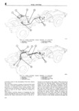
 Next
Next
eep UNIVERSAL SERIES SERVICE MANUAL E y QQ 4 F T T W 77 1 ii ai E9 l l F l 1 e G1 bs I S S sxkm g F iif CjQQ T 7 T l i V l 7 I it 1 j riQT EZIZ I th g VW r r im 3i 2 77 TT L lii 4 N L L 1 4 i i yi 1 ff l l if e as A 5 1 Se 1 l l F 7T4il FF ifiji me I 1 T O 1 4 W rr K i ee a LT l JL e e e if I RF1 s l R W i li 5 1 i W 1 s V I 1 lf 24 M S E I 1 I M A i W N l 11 I 4 i e I 1 U gg c M I ll T lll i ll E1 1 A ll u lv 0 rl I l 1 Jr J1 1 g t ll i i i ligw ll l I s iQ E T eee Timlj L EE QQ Lf Q Ei T 1 1 lll 1 0 0 0 Qi B 14351 FIG E 3 FUEL EVAPORATIVE EMISSION CONTROL SYSTEM HURRICANE F4 ENGINE A Side View B Plan View l Charcoal Canister 6 Vapor Separator or Expansion Tank 2 Purge Line 7 Fucl Gauge 3 Fuel Tank 8 Fuel Line to Fuel Pump 4 Fuel Filler Hose 9 P CZ V Crankcase Valve 54Non Vented Gas Cap 0 eFuel Pump crankcase vent system The charcoal canister in bottom of the canister is fitted with a filter element corporates an integral demand valve which regu that allows fuel tank venting to atmosphere after lates vapors entering the canister as well as a limit vapors are trapped in the activated charcoal fill valve to control air trapping during tank fill The Fuelt lEv lpo air ive Exnissic n Con rio ldSysteCm E 4 Denqand Valve I I 1 Z I mcc po 3 as E O OW ng new OI moi 1 6 par S The demand valve is integral with 1 he canister It is essenitally a combination pressure regulator and E 3 Cam t vacuum relief valve This valve regulates the rate The canister used for the vapor control system has of vapor flowing from the fuel tank into the canister provisions for containing activated charcoal gran The valve consists of a housing a spring loaded ules The material used for the canister body is a diaphragm a diaphragm cover and a vacuum special fuel resistant heat stabilized nylon At the relief valve The operation of the unit is such that top of the canister there is the demand valve which as tank vent pressure increases the diaphragm lifts has connections one vents the vapor to the canister permitting vapor to enter the canister The pres while the other connection joins the canister to the sure under which this occurs is 4 to 6 H20 This purge system These tubes enter 1 he canister on action regulates the flow of vapors into the canister opposite sides of a bafiie which permits uniform under severe soak and operation conditions temp vapor distribution throughout the canister The changes but generally prohibits the How of vapor 111