Ford Parts Wiki | GM Parts Wiki
Home | Search | Browse
Prev

 Next
Next
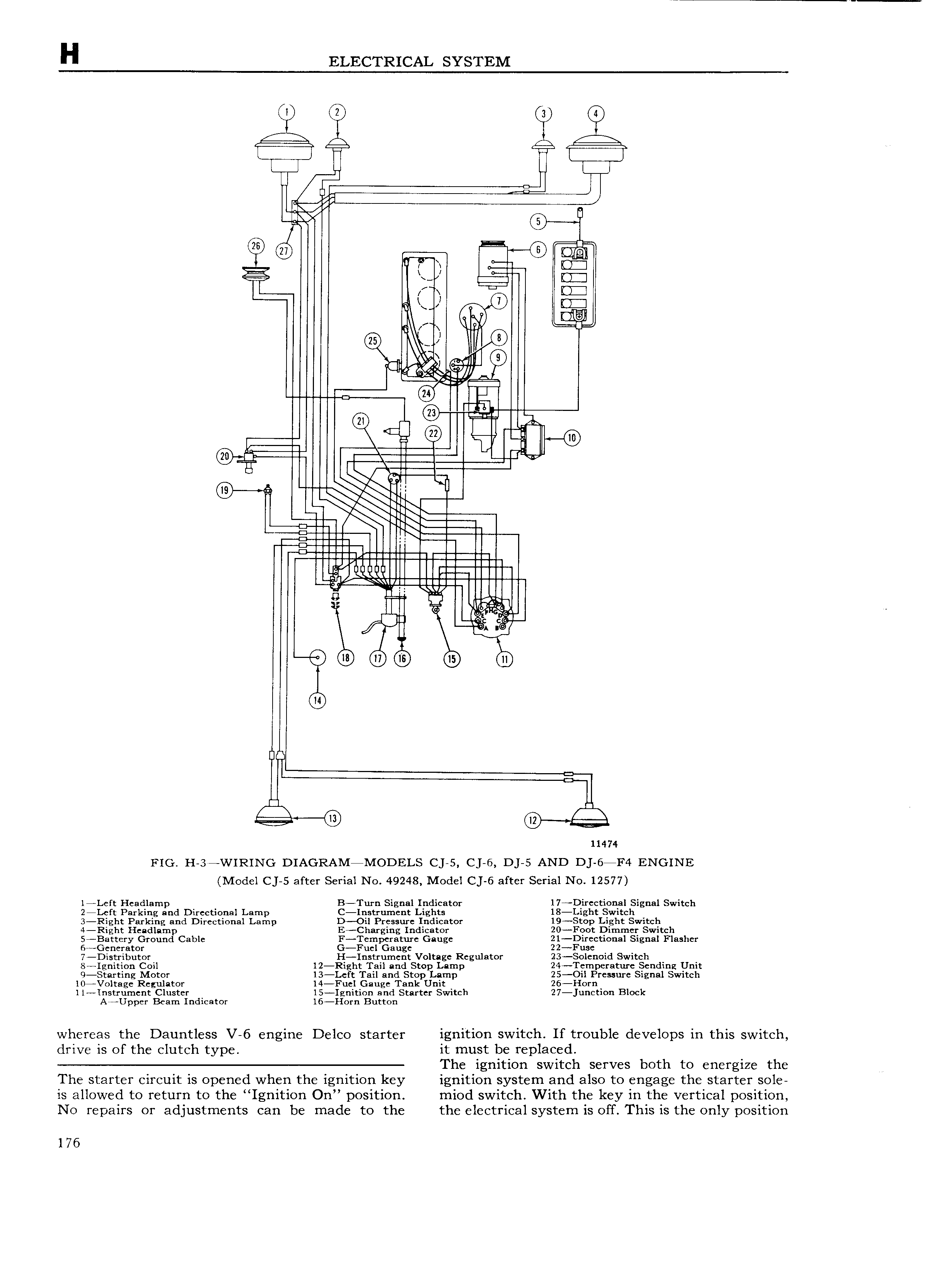
H ELECTRICAL SYSTEM 0 3 Qi m m m T I I l L 0 I 6 III I 6 mm 2 i U1 m KI D I D1 i 0 II V 1 lI 6 444 fw m Ill gig I n II LF m i 1 il w FI I L 11 m nm n nm m I m E I I ll m EE EH iiIpEII II I lIIIIII I I 1EH IIIIIIIIE G I I l III r Loeb 1 3 OD QD GB B M u n 3 g i 11474 rio H 3 WIRING DIAGRAM MODELS cjas c J 6 D 5 AND D5 6aF4 Ewomc Model C 5 after Serial No 49248 Model C 6 after Serial No 12577 l4Left Headlamp B Turn Signal Indicator l7 Dircctio al Signal Switch 2 Lcft Parking and Directional Lamp C Instrumc t Lights 18 Light Switch 3 Right Parking and Directional Lamp D Oil Pressure Indicator 19 Stop Light Switch 4 Right Headlamp E Charging Indicator 20 Foot Dimmer Switch 5 Battery Ground Cable F Temperature Gauge 21 Directi0nal Signal Flasher 6 Generator G Fuel Gauge 22 Fuse 7 Distributor H Instrument Voltage Regulator 23 Solenoid Switch 8 Ignition Coil l2 Right Tail and Stop Lamp 24 Temperature Sending Unit 9 Starting Motor 13 Lcft Tail and Stop Lamp 25 Oil Pressure Signal Switch l0 Voltage Regulator l4 Fuel Gauge Tank Unit 26 Horn ll Instrument Cluster l5 Ignition and Starter Switch 27 junction Block Ar Upper Beam Indicator l6 Horn Button whereas the Dauntless V 6 engine Delco starter ignition switch If trouble develops in this switch drive is of the clutch type it must be replaced The ignition switch serves both to energize the The starter circuit is opened when the ignition key ignition system and also to engage the starter sole is allowed to return to the Ignition On position miod switch With the key in the vertical position No repairs or adjustments can be made to the the electrical system is off This is the only position l 76

 Next
Next