Ford Parts Wiki | GM Parts Wiki
Home | Search | Browse | Marketplace | Messages | FAQ | Guest
Prev

 Next
Next
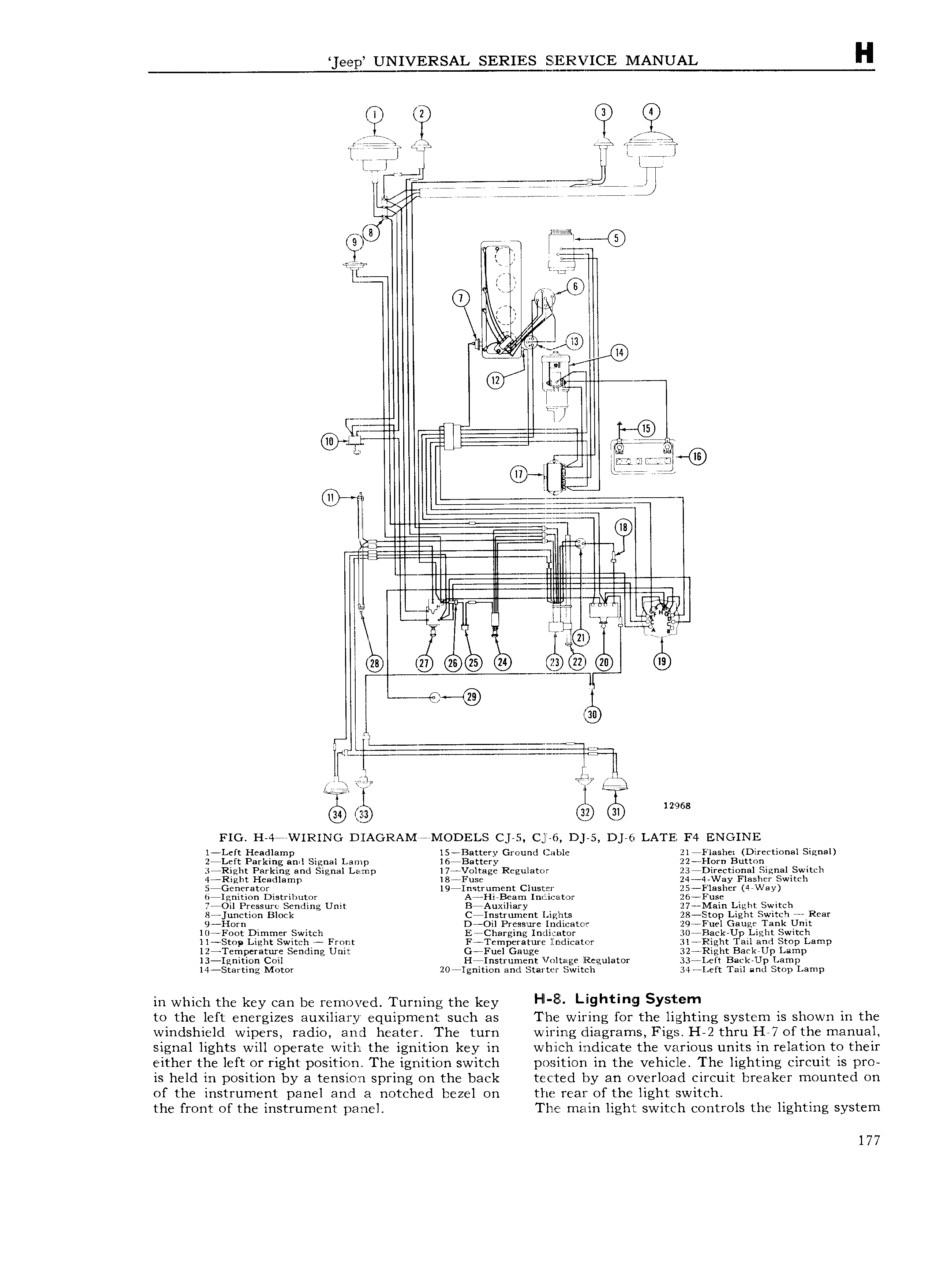
eep UNIVERSAL SERIES S1E RVICE MANUAL H Q Q QR Q T1 gfiQ s gi A tra TJ QI 1 M lr tw A ij iL j J W L ij fQjQi 1o j LLLLL D MDD J rg 8 ii 1gJi an F ty 4 iF V I E I fl W 7 T S Q 11 1 iota t i e 1 1 Q 2 12 Q Lula A i E ci ig L E 1 ZZ 1 2 V I i v E i M H II Il I ZZ ZZ I11 I Il I K II t I KI AML II p LF A 1 i li l vii LI U era Epi ii 2 1 Q3 G0 Q gg g QD 6 m 30 El ti 1 Ti rf ry 12 968 C2 19 FIG H 4 WIRING D1AoRAMaaaa1vroDELs c jas c 6 D S D 5 c LATE F4 ENGINE l Left Headlamp I5 Battery Ground Cable 21 Flashei Directional Signal 2 Left Parking and Signal Lamp l6 l3attery 22 1 orn Button 34Right Parking and Signal Lamp l7AVoltage Regulator 23 iflirectional Signal Switch 4 Right Headlamp l8AFuse 24 4 Way Flasher Switch 5 Generator 19 lfn trument Cluster 25 Flasher 4 Way liilgnition Distributor A4Hi Beam 1n f i a1to1r 26 Fuse 7 Oil Pressure Sending Unit B Auxi iary 27 l Iain Light Switch Kejunction Block Cflnstrument Liglnts 28 Stop Light Switch Rear 9 Horn D Oil Pressure Indicatoir 29 Fuel Gauge Tank Unit l F0ot Dimmer Switch E Charging Inrlicator 30 Back Up Light Switch I l Stop Light Switch Front FATemperature limdicator 31 Right Tail and Stop Lamp I2 Temperature Sending Unit GYFuel Gauge 32 Right Bark Up Lamp 13 Ignition Coil H Instrument Voltage Regulator 33 Left Back Up Lamp l4 Starting Motor 20 Ignition and Starter Switch 34 Left Tail and Stop Lamp in which the key can be removed Turning the key HI 8 Lighting SY l m to the left energizes auxiliary equipment such as The wiring for the lighting system is shown in the windshield wipers radio and heater The turn wiring diagrams Figs H 2 thru H 7 of the manual signal lights will operate with the ignition key in w hi ch indicate the various units in relation to their either the left or right position The ignition switch p o iti on in the vehicle The lighting circuit is pro is held in position by a tension spring on the back tected by an overload circuit breaker mounted on of the instrument panel and a notched bezel on the rear of the light switch the front of the instrument panel I h1e main light switch controls the lighting system 177

 Next
Next