Ford Parts Wiki | GM Parts Wiki
Home | Search | Browse
Prev

 Next
Next
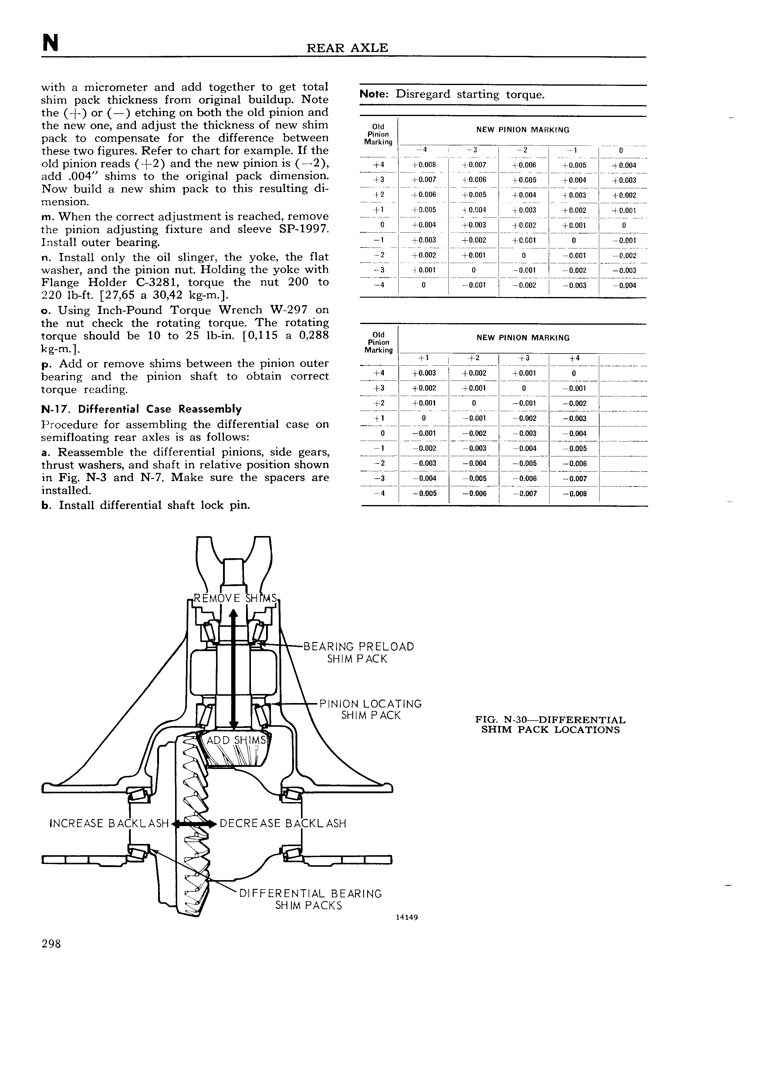
N REAR AXLE with a micrometer and add together to get total shim pack thickness from original buildup New lsfegaf S f g wfque the or etching on both the old pinion and M the new one and adjust the thickness of new shim Poi NEW PINION MARKING pack to compensate for the difference between M Q g these two figures Refer to chart for example If the nj4 2 i el W 0 old pinion reads 2 and the new pinion is 2 4 0 000 0 007 03067 0 005 R iiiihhm add 00 l shims to the original pack dimension QQR Rldjbgg j U6g Ejhnbsn Q ib64r 0f063r Now build a new shim pack to this resulting d1 mk rr MM mst R 605 U 6 H b e m nSiOn 1 3005 j Q i 9i iPfl m When the correct adjustment is reached remove i fi l 0 Y0lL I p 0U3 i iR 09 i li 90l the pinion adjusting fixture and sleeve SP 1997 q iP 004 jl i 9i JCq q i I jP q9L i gw Iristail outer bearing iP i ii i L i H l H 9F n Install only the oil slinger the yoke the flat j i f g j L n r Wiih jI jVwiw 0 I Q i washer and the pinion nut Holding the yoke with 2 I0 001 0 0 001 0 002 0 003 Flange Holder C 3281 torque the nut 200 to RZTI0 WKW Hi W i Q 5 5i i i Q 220 lb ft 27 65 a 30 42 kg m 0 Using Inch Pound Torque Wrench W 297 on the nut check the rotating torque The rotating torque should be 10 to 25 lb in 0 115 3 0 288 PQ n New I INION MARKING l g H1 Mairtling p Add or remove shims between the pinion outer t i If i3 ji bearing and the pinion shaft to obtain correct JL gjQ gg jfPf9 lff f9Li f fl V iv i torque reading j i jpgqgg ijpglli Will 0 00l N 17 Differential Case Reassembly ji 0091 q 0f9L j i 9f Procedure for assembling the differential case on l 1 3 0fPl 29 09 wi semifloating rear axles is as follows 9 P q9l P 9g jPf9i iPf9l a Reassemble the differential pinions side gears jL njfgi j9 TH 9i ljfpL thrust washers and shaft in relative position shown niQ9irV iijggi i j1i005 M 0 006 in Fig N 3 and N 7 Make sure the spacers are AA i 0 004 0 005 0 006 0 nniww Installed 4 0 06 LbT606rIIi 0 0HR5 R RRWU I b Install differential shaft lock pm l BEARING PRELOAD SHIM PACK F I INIoN LocATINo m N SHIM P ACK FIG N s0 DIFFERENTIAL smivr 1 Acx LOCATIONS q I K ET INCREASE BACI I ASH DECREASE BACKLASH et Y I 51 DIFFERENTIAL BEARING I j SH IM PACKS 14149 298

 Next
Next