Ford Parts Wiki | GM Parts Wiki
Home | Search | Browse
Prev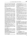
 Next
Next
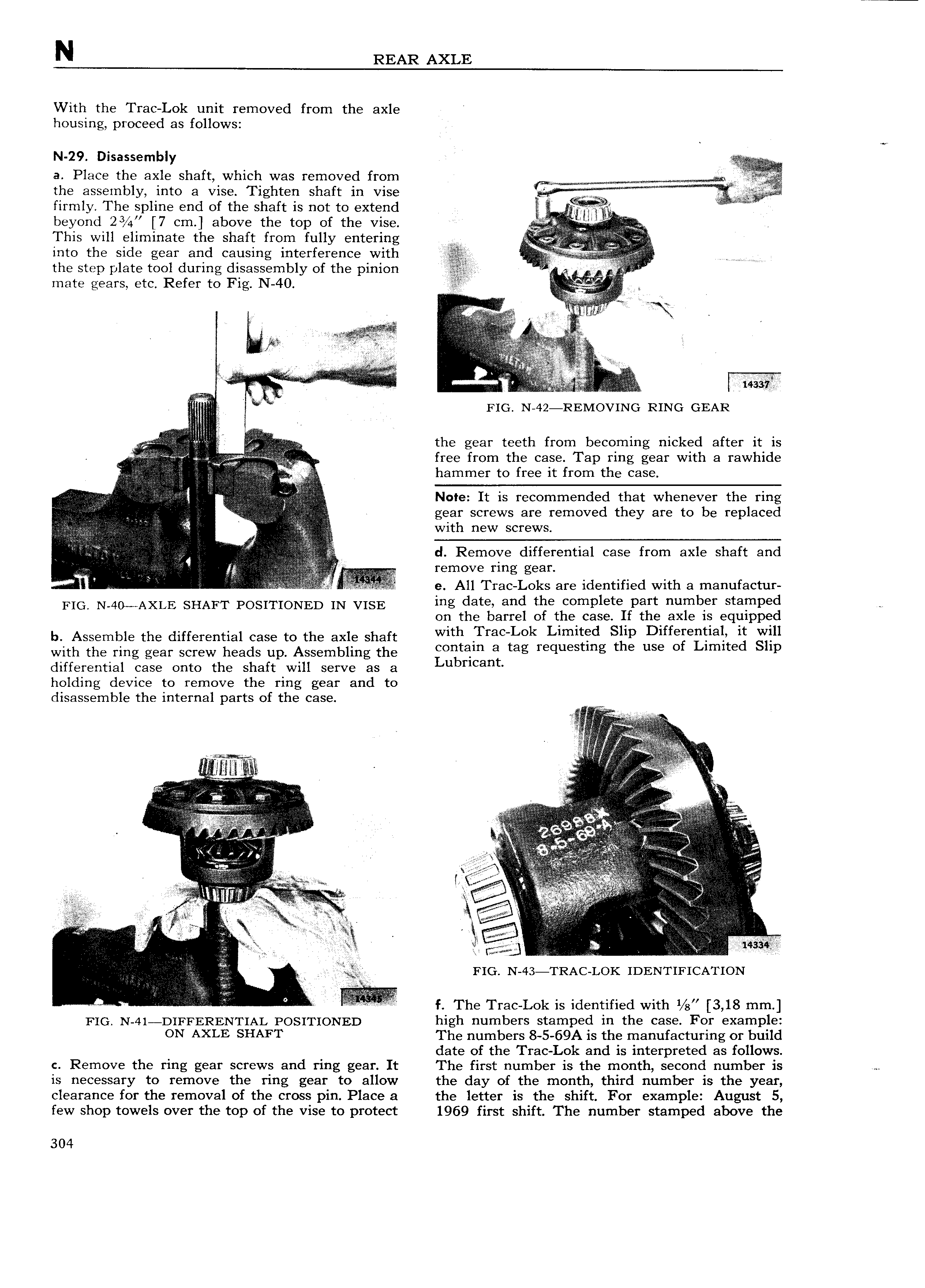
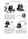
N REAR AXLE With the Trac Lok unit removed from the axle housing proceed as follows N 29 Disassembly a Place the axle shaft which was removed from the assembly into a vise Tighten shaft in vise firmly The spline end of the shaft is not to extend A i n beyond 2 7 cm above the top of the vise E This will eliminate the shaft from fully entering into the side gear and causing interference with V the step plate tool during disassembly of the pinion i i l mate gears etc Refer to Fig N 40 I V c I e J3 I i fi Eg E e I f V l r 2 v i I i i l l i l i I l ll ri r i l E i L i FIG N 42 REMOVING RING GEAR V r the gear teeth from becoming nicked after it is x free from the case Tap ring gear with a rawhide Qzij r Q V I hammer to free it from the Case V V Y EE if V eV J f l 5 I Note It is recommended that whenever the ring l 5 Qy Z gear screws are removed they are to be replaced fijt r 2i I if if l i with new screws I VI I i d Remove differential case from axle shaft and 1 if E I f m v me gw 1 i R e A11 Trac Loks are identified with a manufactur FIG N 40 AXLE SHAFT POSITIONED IN VISE ing date and the complete part number stamped on the barrel of the case If the axle is equipped b Assemble the differential case to the axle shaft Wlth mc LOk Llmmfid SEP D lffegeillab g gain with the ring gear screw heads up Assembling the contain 3 tag requestmg t 8 use O mute lp differential case onto the shaft will serve as a Lubrlcant holding device to remove the ring gear and to disassemble the internal parts of the case g A t t Ei e E t i I rl li v ilnn I i i Q E l i I I I x alz i X 5 1 ir Q 5 I lr t E V Q K la e e llillffiif s at i ft Y l i V I V r I it er I fpwtw if V I t i i e r t tteeit 1 I I e Iycc FIG N 43 TRAC LOK IDENTIFICATION 9 A T s The rmC LOk is identified with W 3 18 mm FIG N 41 DIFFI ERENTIAL POSITIONED high numbers stamped in the case For example ON AXLE SHAFT The numbers 8 5 69A is the manufacturing or build date of the Trac Lok and is interpreted as follows c Remove the ring gear screws and ring gear It The first number is the month second number is M is necessary to remove the ring gear to allow the day of the month third number is the year clearance for the removal of the cross pin Place a the letter is the shift For example August 5 few shop towels over the top of the vise to protect 1969 first shift The number stamped above the 304