Ford Parts Wiki | GM Parts Wiki
Home | Search | Browse
Prev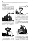
 Next
Next
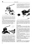
eep UNIVERSAL SERIES MANUAL N V i 5 V A 3 i V F f E VV V i V 2 V 4 LI gigwtw c i A I f y O EL iiiffiijy V V Z P M 4 N n F V Z 1 I GZ 4 4 L Z V V vv jn A Q 1 aa T w gg 2 if Q Zi I tf V it M 2 V A il lA V Q A I z T YZ Q Y I V Y V K L V V i E if R L L v L LL V l V V A V ll k S pl p E i 34 Zii i Q3 gx Z V V FIG N 46 INSTALL1NG STEP PLATE TOOL T L FIG N 44 REMOVING SNAP RINGS ig FROM CROSS PIN K iii manufacturing date is the complete Trac Lok as sembly part number e QT A g It is recommended that when referring to the i L 1 Trac Lol obtain the complete part number and A Q W build date To do this it will be necessary to wipe off the lubricant from the case See Fig N 43 rV V h Reposition differential case onto axle shaft as L fl l f L shown Remove the two snap rings from the cross Ii A14351i pin Use two screw drivers and push the rings free p N T from the cross pin Place 3 shgp towel behind Flloi N V4i INS ALLING GE AR ROTATING TOOL the case to prevent the snap rings from flying out of the case Refer to Fig N 44 I M f V V V t if S xw I Wi V i xii X i r t Vv A if A ii ji ji Q N ii is 2 V I iii i A gt if Q t f i t z i S S 2i A 41 i if i A w Q Z U FIG N 45 REMOVING CROSS PIN we is i i T i Ja 1 Remove the cross pin Use at hammer and punch FIG N 48 THREADING FORCING SCREW as shown to remove the cross pin from the case INTO RQTATIIQG TOOL Note A gear rotating tool C 4142 is required to I h f d h h h service the Trac Lok diferential The Tool consists Pl rt t 9 Orcmg scfew Own t mug t Q top of four parts a Handle Pawl Forcing Screw and and thread mm the gear rotating tOO1 Step Plal5 Noireae Before using the forcing screw be sure the i Assemble the Step plate tool into the bottom threads are lubricated with a fine coat of oil Also Side gearq as shown in Fig N 46 appl y a small spot of grease to the centering hole k Position the gear rotating tool into the top gigfmigg step plate before It contacts the fm cmg side gear as shown in Fig N 47 QQ Q L MMMM 305