Ford Parts Wiki | GM Parts Wiki
Home | Search | Browse
Prev
 Next
Next
11111111
111111
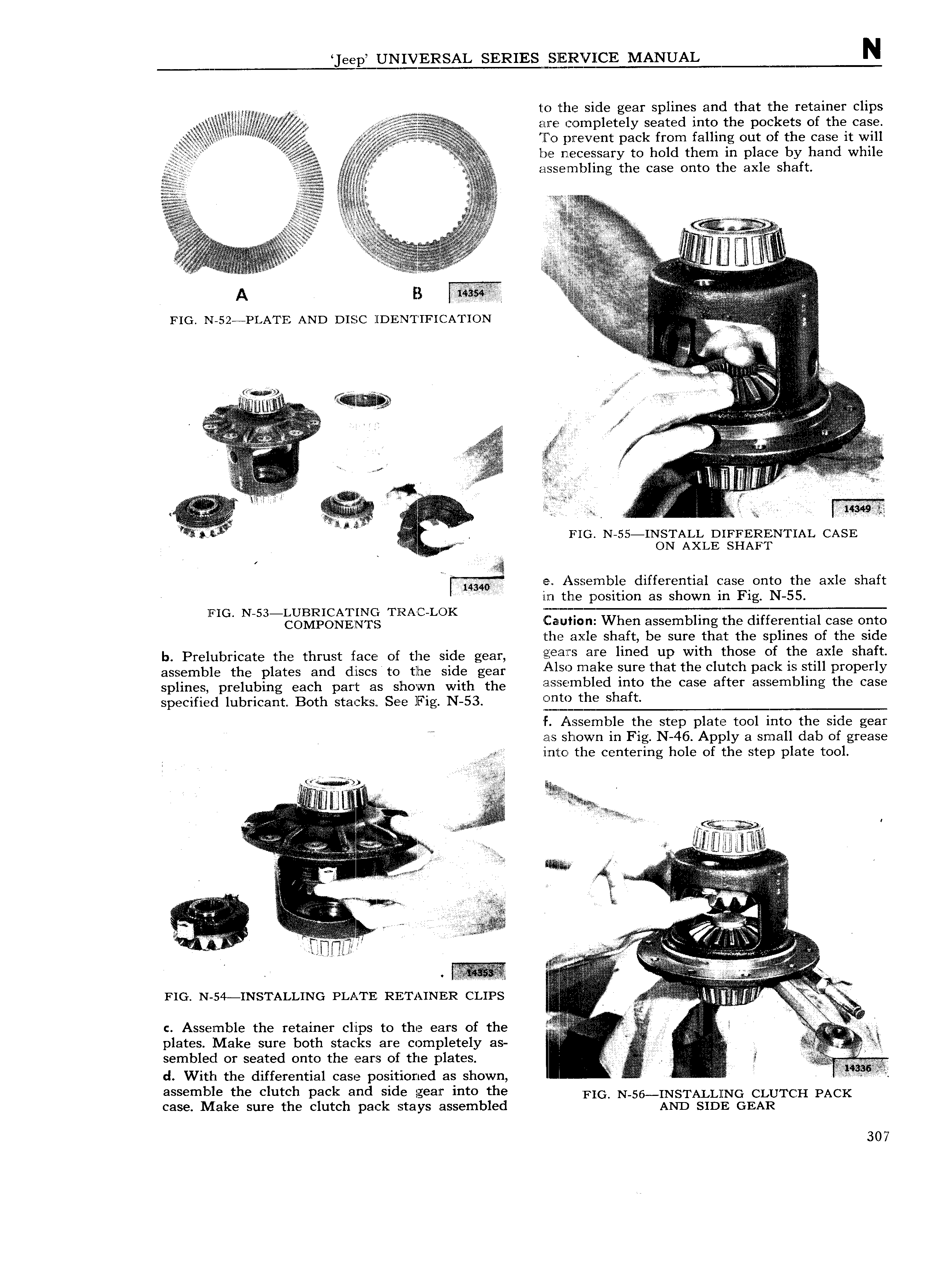
eep UNIVBSAL SERIES l l jgQCE MANUAL N 11 1 to the side gear splines and that the retainer clips rg rm 1 1 1 1 11e 1 1 1 figs are completely seated into the pockets of the case Tgiii ff ji if Y v j X M s r1 1 i 1 fo prevent pack from falling out of the case lt will r ll lf 1 11 ld 11 1 b 11 11 111 g 1g Q5 5 yr l11 4E l l1E C SSHI y to O t I l l 1I 1 p 3C y HD W l 1 A 1 h h 1 lyft 11 11 11 1 1 1 5 111 1111 sembl1ng t e case onto t e ax e s a ii 1 1 1 1111 aa1l 1 111 1 1 1 11 1 11 1111 av 1 i l iii i s A 1 1 1 1 M in 1 A 1 A V K A B l ssttr l 1 1 E 1 1T t 11 T FIG N 52 PLA l E AND DISC l DENTIFI CATION 1 11 1 1 1 1 1 ii 1 1 V p E 1 111 Vi gjg 1 A l v1 1 11 1 1 U Z lg fi Iii v 1 1 41 w 2 1 ii 1111i i 1 i 1 z 1 1 1 7 tl E 1 111 1 11 11 11 11 f t V 1 V111 E 1 A 1 s 1 4 1l1 1 1111 1 e 1 V 1 i 11 A 1 1 V i 1 i Z 1 l 1 f 1 11 I t 11 p X 1 1 1 1 ts s1 9 si i j 1 FIG N 55 INSTALL DIFFERENTIAL CASE yr ON AXLE SHAFT A 1 e1 Assemble differential case onto the axle shaft 114 w 1 1 1 1 1 lllTl the position as shown in Fig N 55 1 T AC LDK f T MM T MMf M FIG N 53 R l C a ut1 n When assembling the differential case onto the axle shaft be sure that the splines of the side b Prelubricate the thrust face of the side gear i ai S ar lmed glp Tlnthl thclfe Ci id t 1Xl Sha assemble the plates and discs to the side gear fo me uY t att eclgtc Pak 1 1 PBOPEYY splines pmlubmg each part as Shown Wlth the a1s eInbled 1nto the case a ter assem Ing t e case specified lubricant Both stacks See Fig N 53 Shaft F Assemble the step plate tool into the side gear as shown in Fig N 46 Apply a small dab of grease H ilZ Ili Cl the centering hole of the step plate tool f 1 1 1 f 1 i 1 A i Ys if 11 1 1 1 1 1 1 11 11 1 1 1 1 1 A lj ill QQ ff V i 1 V a a1 1 I 1 L 3 1 gi M 5 1 11 1 1 111 1 1 mw VV I J if 11111 11111 l A w 11 1 iJi11 I 1 1 1 1 1 11111111 1 11111 I 1111 1 1 6 3 r AE 1 II M r1 1 11111 1 1 1 e 1 I F 1 1 1 f 1 I ms i 111 i ij 1i 11 11 S 1 1 11 1 I 1 1 1 11 1 T 1 1 111111 FIG N 54 INSTALLING PLATE RETAINER CLIPS I r i 11 V 1 1 1 I c Assemble the retainer clips to the ears of the L 1 1j i1 13 plates Make sure both stacks are completely as n 1 V 1 E 11 semblecl or seated onto the ears of the plates 1 1 V d With the differential case positioned as shown if A if assemble the clutch pack and side gear into the F G N 56 INSTALL NG CLUTCH PACK case Make sure the clutch pack stays assembled AND SIDE GEAR 307