Ford Parts Wiki | GM Parts Wiki
Home | Search | Browse | Marketplace | Messages | FAQ | Guest
Prev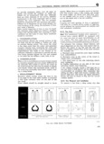
 Next
Next
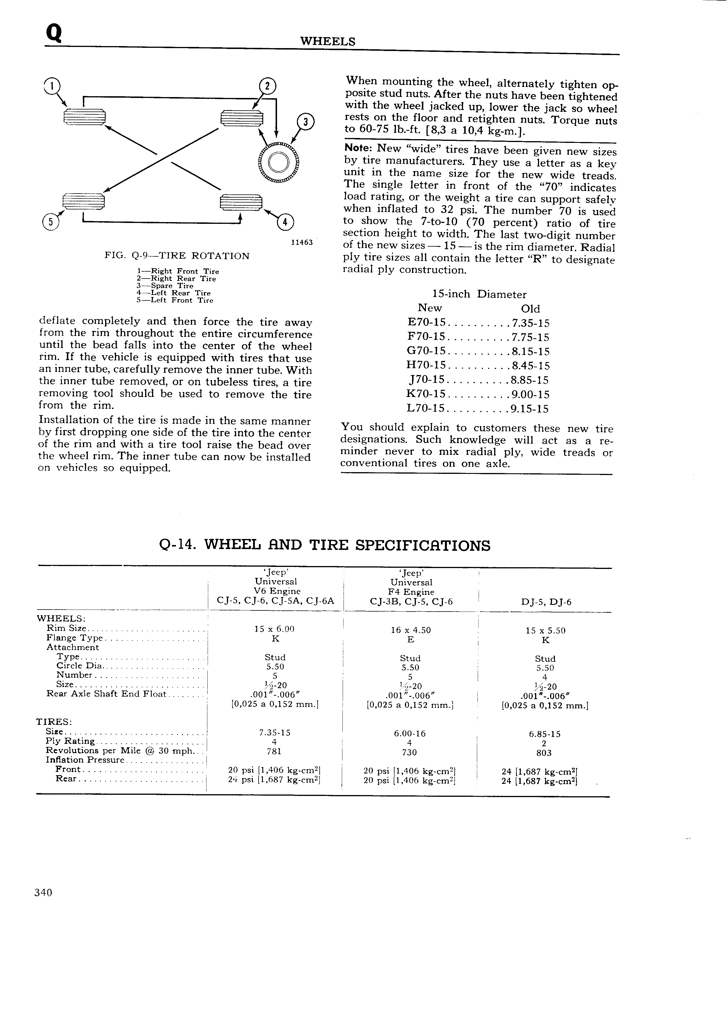
Q WHEELS I When mounting the wheel alternately tighten op Q posite stud nuts After the nuts have been tightened with the wheel jacked up lower the jack so wheel rests on the floor and retighten nuts Torque nuts t0 60 75 lb ft 8 3 a 10 4 kg m Note New w1de tires have been given new sizes by tire manufacturers They use a letter as a key unit in the name size for the new wide treads The single letter in front of the 70 indicates load rating or the weight a tire can support safely when inflated to 32 psi The number 70 is used t0 h0W the 7 to 10 70 percent ratio of tire section height to width The last two digit number 11463 of the new sizes 15 is the rim diameter Radial FIG Q 9 TIRE ROTATION ply tire sizes all contain the letter R to designate 1 ght r m TTire radial ply construction 2 ight ear ire gQ 15 inch Diameter et ront ire New deflate completely and then force the tire away E70 15 7 35 15 from the rim throughout the entire circumference F70 15 7 75 15 until the bead falls into the center of the wheel G70 15 8 15 15 rim If the vehicle is equipped with tires that use H7O 15 84545 an inner tube carefully remove the inner tube With 5 the inner tube removed or on tubeless tires a tire J70 1 8 8545 removing tool should be used to remove the tire K7O 15 900 15 from the rim L70 15 9 15 15 Installation of the tire is made in the same manner You Should explain to Customers these new the by f1 1rSt drOpp g O Side 05 ttf tire Ingo ghegentcr designations Such knowledge will act as a re 0 t ibut an git a tm SO mise t E ga Ci eg minder never to mix radial ply wide treads or the w ee rim evinner tu e can now e insta e Conventional tires On one axle on vehicles so equipped Q 14 WHEEL HND TIRE SPECIFICHTIONS Univiiisal Universal V6 Engine F4 Engine CJ 5 C 6 Cj 5A Cj 6A C 3B CJ 5 CJ 6 I Dj 5 D 6 Kiaarihm Rim Size 15 x 6 00 16 x 4 50 I 15 x 5 50 Flange Type K l E K Attachment Type Stud j Stud Stud Circle Dia 5 50 5 50 5 50 Number I s 1 5 4 size zo 24 20 20 Rear Axle Shaft End Float 0O1 006 001 006 O01 0O6 0 025 a 0 152 mm 0 025 a 0 152 mm 0 025 a 0 152 mm TIRES S 1 7 35 15 6 00 16 6 85 15 Plgrcliating 4 I 4 2 Revolutions per Mile 30 mph A 781 730 803 Inflation Pressure Front 20 psi 1 406 kg cm 20 psi 1 406 kg cm2 24 1 687 kg cm2 Rear 24 psi 1 687 kg cm2 20 psi 1 406 kg em 24 1 687 kg cm2 340